Removal and installation of the air filter
Disconnect the negative cable from the battery. Loosen the clamp and remove the air duct connecting the air filter to the air flow meter. Remove the POS sensor and its gasket from the upper cover of the air filter. Unscrew the six Phillips screws securing the air flow meter, but do not remove it. Unscrew the captive screw and remove the fuel filter. Unscrew the two nuts securing the air filter housing, as well as the screw of its lower fastening to the inner wing panel. Remove the air intake hose attached to the bottom of the shield. Move the top cover of the filter aside, remove the air flow meter and move it to the side, remove the top cover and the filter element. Remove air filter. Clean filter before installation. Install in the reverse order of removal. Make sure the air flow meter gasket is installed correctly
NOTE: From mid-September 1980 on cars manufactured in Sarlouis (index SL), a spacer sleeve 3 mm high was installed between the air filter and the thermostat.
Removal and installation of the dispenser-distributor of fuel
Disconnect the negative cable from the battery. Place a rag under the hose fitting from the control pressure regulator, release it to relieve pressure in the system. Disconnect all fuel lines from the dispenser (rice. 2.114). Unscrew the three mounting bolts and remove it as an assembly with the air flow meter. Clean mating surfaces and fittings before installation. Install and fix the mixture regulator assembly between the air flow meter and the dispenser-distributor. Connect all hoses to the dispenser by installing new washers on each side of the fitting. Avoid excessive force when tightening fittings. Connect the negative battery cable. Check fuel pressure and engine idle speed.
REMOVING AND REFITTING THE CONTROL PRESSURE REGULATOR
Disconnect the negative cable from the battery and connector block 1 (rice. 2.115) regulator. Place a rag under the fuel line fittings, relieve pressure and remove these fuel lines. Loosen the two hexagon socket screws and remove the pilot pressure regulator. Before installation, wipe the mating surfaces and fittings. Reinstall the regulator and secure it with two bolts, apply sealant to the screw heads. Install two new washers on the ends of the pipelines, one for the fitting, one for the screw. Avoid excessive force when tightening fittings. Connect the connector block and negative battery cable.
Removal and installation of a starting nozzle
Disconnect the negative cable from the battery and connector block 1 (pic. 2.116).
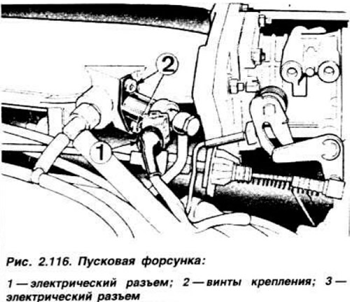
Disconnect the union and the fuel supply pipe, having previously relieved the fuel pressure. Unscrew the two screws 2 securing the injector and remove it. Wipe mating surfaces before installation. Install a new gasket, tighten the nozzle mounting screws and apply sealant to them. At the end of the pipeline, install two new washers, one for the fitting, one for the screw. Do not use excessive force when tightening the fitting. Connect the connector block and negative battery cable. Start the engine and check the fuel system for leaks.
Removal and installation of the valve of additional air supply
Disconnect the negative cable from the battery, connector block 3 (pic. 2.117) and two hoses from the valve.
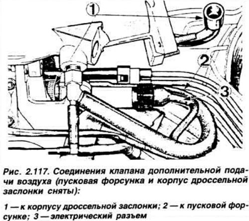
Loosen the two hexagon socket screws and remove the valve. Installation is carried out in the reverse order of removal. Apply sealant to the screws.
Removal and installation of fuel injectors
Disconnect the negative cable from the battery. Unscrew the fuel supply fittings to the injectors. Loosen the screws securing the holders and remove the injectors. Clean all fittings, check the position of the nozzle seals, install the nozzles and secure them with holders. Connect fuel lines and battery.
Removal and installation of injector fuel lines
The flexible hoses of the injectors are connected to metal tubes by couplings, which must not be disassembled. In addition, on parts of XR 3i vehicles, the fitting tips are connected to plastic flexible hoses with special connectors, the disassembly of which is also prohibited. Before removing the high pressure fuel lines, disconnect the negative battery cable and disconnect the fuel lines from the injectors, then disconnect them from the dispenser and remove the fuel lines as a set. Thoroughly clean the fittings before installation. Check that the fuel lines are not kinked or damaged. Install in the reverse order of removal, using two new gaskets on each fitting, do not apply excessive force when tightening. Connect the negative wires to the battery.
Removal and installation of the fuel pump
Place the car on a viewing hole or lift. Disconnect the negative cable from the battery. For fitting 4 (rice. 2.114) place a rag on the fuel line from the control pressure regulator and relieve pressure in the system. loosening the fitting. Clamp the fuel supply hose to the fuel pump with a clamp so that the fuel does not drain into the tank after the fuel line is disconnected and so as not to damage the fuel line. Place a container under the fuel supply fitting, remove the clamp and fuel line. Seal the fuel line opening. Disconnect both connector blocks from the pump and disconnect the fuel delivery line from it. Loosen the nut on the bracket and remove the pump. Thoroughly clean fittings and couplings before installation. Reinstall the pump, making sure that the rubber coupling is installed correctly. Connect the injection hose and both connectors, then the fuel supply hose and remove the clamp from the hose.
Lower the vehicle and tighten the fuel supply fitting to the control pressure regulator Connect the battery, start the engine and check the fuel system for leaks.
Removal and installation of the fuel pressure accumulator
Place the vehicle on a viewing ditch or lift. Disconnect the negative cable from the battery. Put a rag under fitting 2 (rice. 2.114) supply fuel to the control pressure regulator and, slowly releasing it, relieve pressure in the system. Place a container under the accumulator fittings and unscrew them. Loosen the screw securing the drive bracket and remove it together with the drive. Before installation, wipe the fittings, install the accumulator in the reverse order of removal, start the engine and check the tightness of the connections.
Removal and installation of the fuel filter
Disconnect the negative cable from the battery. Put a rag under fitting 2 (rice. 2.114) supply fuel to the control pressure regulator and, slowly releasing it, release the pressure. Place a container under the fuel filter fittings and unscrew them. Loosen the filter clamp and remove the filter. Installation is carried out in the reverse order of removal, start the engine and check the tightness of the connections.
Visitor comments