Contents: Throttle body ↳ Additional air supply valve ↳ Electromagnetic starting nozzle ↳ Fuel injectors ↳
Throttle body
The throttle body (Fig. 2.105) is installed between the metering distributor and the intake manifold.
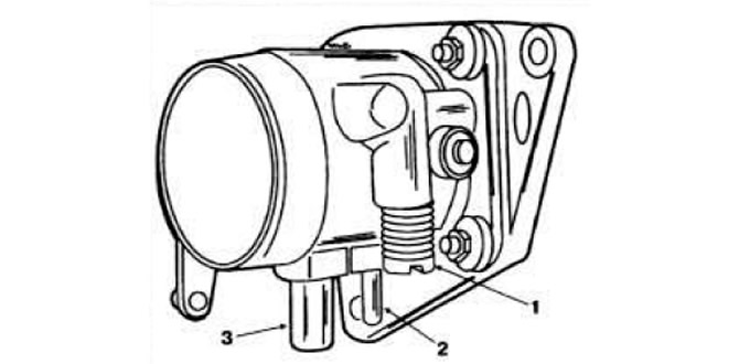 Fig. 2.105. Throttle body.
1 - idle speed adjusting screw; 2 — branch pipe of the vacuum supply hose to the fuel dispenser-distributor; 3 — additional air supply hose branch.
The throttle valve is never completely closed to avoid jamming in the air intake cone when it cools down. It is prohibited to violate the factory adjustment of the throttle valve opening.
Additional air supply valve
The additional air supply valve (Fig. 2.106) operates on the principle of the accelerated idle device of carburetor engines, providing an additional amount of air when warming up a cold engine.
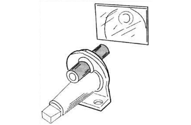 Fig. 2.106. Operating principle of the additional air supply valve.
1 — shoe; 2 - bimetallic spring winding; 3 - bimetallic spring; 4 — rotary valve.
When starting a cold engine, the additional air supply channel is open. As the engine warms up, the bimetallic spring 3 turns the valve 4 and the air supply channel gradually closes. On a hot engine, the valve is closed.
In addition, the supply of additional air is regulated by the pressure disk of the air flow meter, the movement of which leads to the rise of the metering valve, and consequently to an increase in the crankshaft speed (with the throttle valve closed).
Electromagnetic starting nozzle
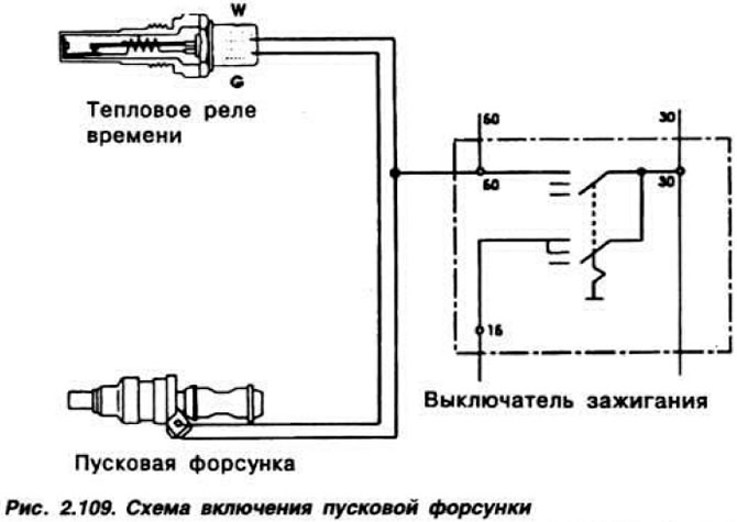
The electromagnetic starting injector (Fig. 2.107) is designed to inject an additional amount of fuel into the intake manifold when starting a cold engine. It is controlled by a thermal time relay (Fig. 2.108), which closes and opens the starting injector's electrical circuit depending on the engine temperature and the duration of the start (Fig. 2.109).
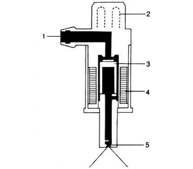 Fig. 2.107. Section of the starting nozzle.
1 — fuel supply pipe; 2 — shoe; 3 - core; 4 - winding; 5 - swirl atomizer.
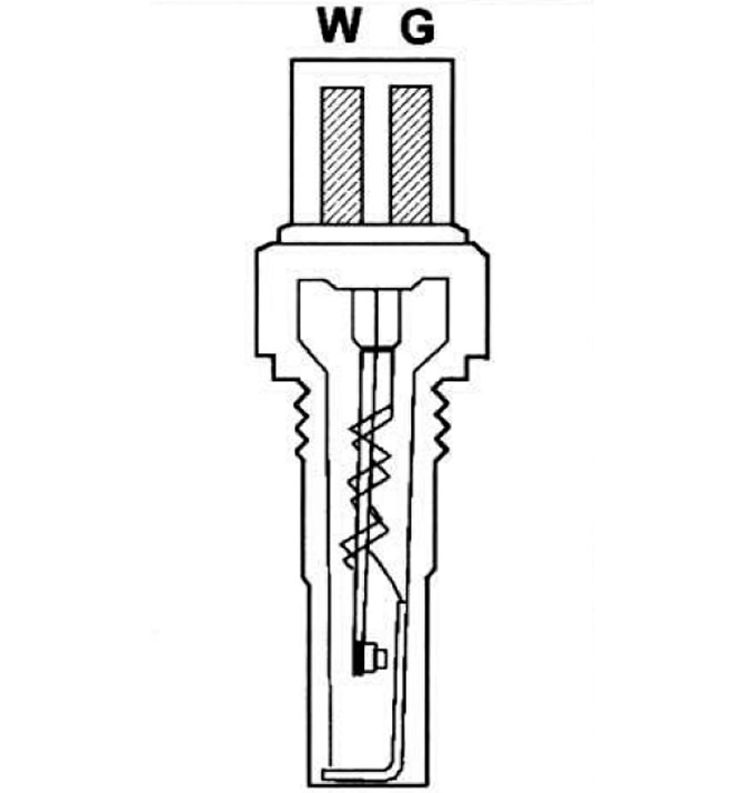 Fig. 2.108. Section of the time relay thermometer.
1 - contact; 2 - bimetallic spring; 3 - winding.
Fuel injectors
Fuel injectors (Fig. 2.110) inject fuel into the cylinders under a pressure of 3.2-4.0 kgf/cm², ensuring fuel atomization in the form of a cone of a certain shape.
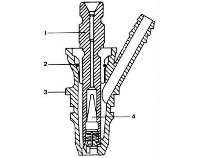 Fig. 2.110. Section of fuel injector.
1 - sprayer body; 2 - sealing ring; 3 — nozzle body; 4 - conical filter.