Contents: Idle speed adjustment ↳ Air flow meter ↳ Fuel pump ↳ Checking the performance of the fuel… ↳ Checking fuel pressure ↳ Checking the control pressure ↳ Checking residual pressure ↳ Control pressure regulator ↳ Additional air supply valve ↳ Thermal time relay ↳ Starting nozzle ↳ Fuel injector ↳
Idle speed adjustment
Adjustment of the engine idle speed is carried out with the engine warmed up to operating temperature, with the ignition timing correctly set, the air filter element clean and the electrical consumers switched off. On cars with an automatic transmission, the selector lever must be set to the "P" position. Connect the control tachometer according to the operating instructions, start the engine and measure the crankshaft speed at idle, which should be within 750-850 rpm, otherwise make adjustments. To do this, let the engine run for 30 seconds with a crankshaft speed of 3000 rpm, then switch it to idle. Rotate screw 1 (fig. 2.105), adjust the crankshaft speed.
NOTE: If the fuel lines were disconnected from the fuel injectors before adjustment, the engine must run several times at 3000 rpm and at idle for at least 2 minutes before adjustment.
To adjust the carbon monoxide (CO) content in the exhaust gases, connect the gas analyzer, unscrew the plug covering the CO content adjustment screw on the metering distributor housing, and let the engine run for 30 s at a crankshaft speed of 3000 rpm, then switch it to idle. Turn the adjusting screw with a 3 mm Allen key (Fig. 2.111), bring the CO content in the exhaust gases to the standard of 1.0-1.5%.
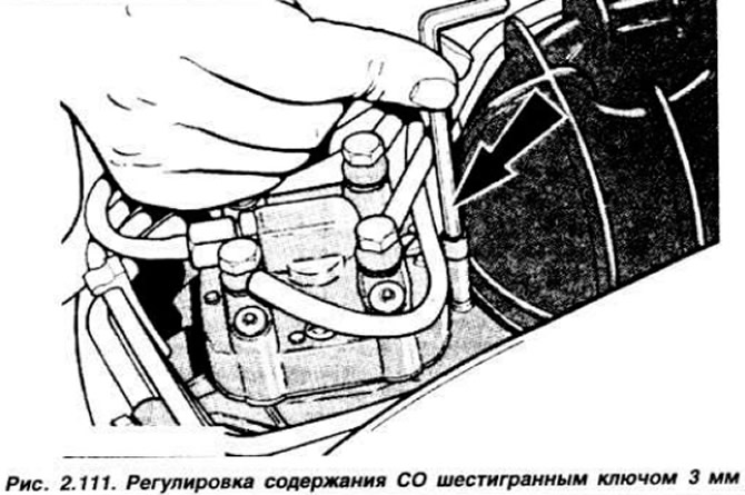
NOTE: When adjusting, do not remove the key from the adjusting screw or press on it, do not increase engine speed without removing the key from the screw.
The throttle opening is adjusted at the factory and is not adjusted during operation.
Air flow meter
Disconnect the air duct from the air flow meter to gain access to its disk. Check the operation of the metering valve drive lever in the following order. Turn on the starter for about 10 s. Use a screwdriver or magnet to lift the pressure disk of the meter (Fig. 2.112).
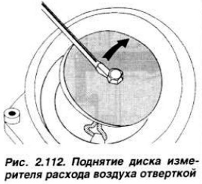
The lever should provide equal resistance to movement within the entire stroke of the disc. When the disc is quickly lowered, the lever should not provide resistance. Otherwise, replace the air flow meter. If the lever is difficult to move upward, this indicates that the valve is jammed, so it is necessary to replace the fuel metering valve. After this, check the engine oil temperature, which should be above 50°C. Start the engine for about 15 s and check the position of the disc in the diffuser. The top of the disc should be at the same level or no more than 0.5 mm lower than the narrowest part of the diffuser (Fig. 2.113).
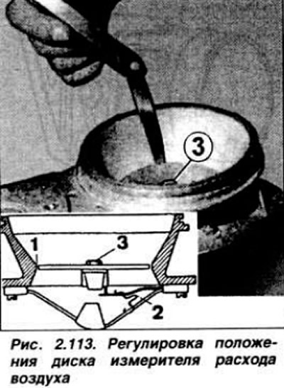
To adjust its position, lift the disc up and squeeze or release the wire clamp 2 located under the disc to obtain the correct position of the pressure disc. Do not bend the leaf spring when the disc stops. Check the engine idle speed as described above.
Fuel pump
Disconnect the connector block from the pump and connect the test lamp to the connectors of the wire block. Turn on the ignition. The test lamp should light up. If it does not light up, check the wiring and the fuel pump relay.
Checking the performance of the fuel pump
Disconnect the fuel drain pipe 3 (Fig. 2.114) from the fuel distributor into the tank, and connect a short hose in its place, the end of which is lowered into a measuring vessel.
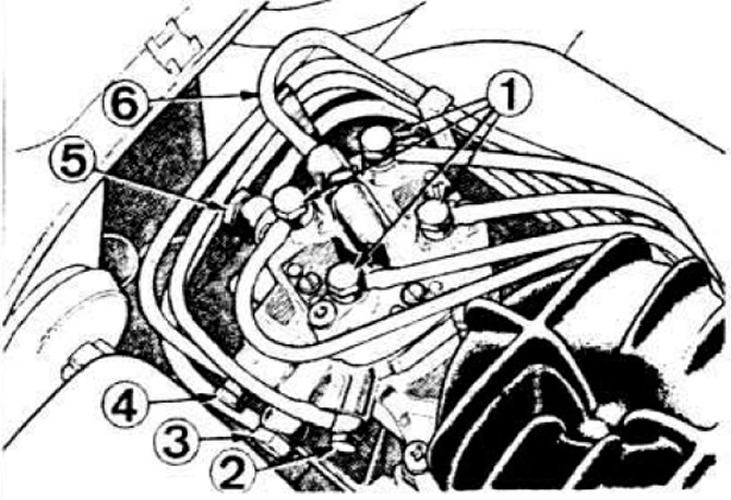 Fig. 2.114. Fuel dispenser-distributor fittings.
1 - to fuel injectors; 2 - to the starting nozzle; 3 - drain fuel; 4 — from the control pressure regulator: 5 — fuel supply; 6 - to the control pressure regulator.
Disconnect the fuel pump relay and short-circuit the "30" and "87" plugs of the wiring block with a short jumper (the relay is located on the front body panel behind the glove compartment). Turn on the ignition and let the pump run for 30 s. The amount of fuel entering the tank must be at least 750 cm³. Otherwise, check the pump and fuel filter. Connect the fuel pump relay block.
Checking fuel pressure
Relieve the pressure by loosening the fitting 3 (Fig. 2.114) of the fuel drain hose from the control pressure regulator, after placing a rag underneath it.
Disconnect fuel line 2 (Fig. 2.115), connecting the control pressure regulator to the metering distributor, and instead connect a control pressure gauge with a tap for measuring both the flow pressure and the inlet pressure.
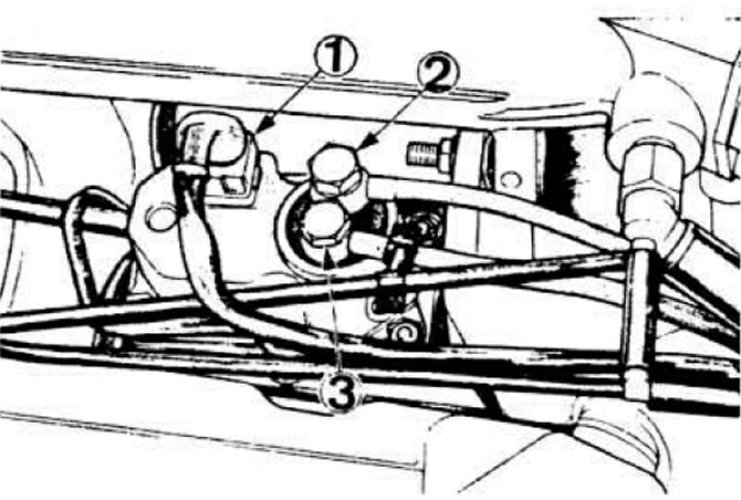 Fig. 2.115. Control pressure regulator connections.
1 — electrical connector: 2 — fuel supply nipple; 3 — fuel drain nipple.
Remove air locks. To do this, start the engine, set the pressure gauge valve to the position for monitoring the flow pressure and lower the pressure gauge so that it hangs on the hoses. Open the pressure gauge valve. Start the engine and set the idle speed. Read the fuel pressure in the system on the pressure gauge, which should be within 4.7-5.5 kgf/cm². Otherwise, find and eliminate the cause of the pressure deviation from the norm or replace the dispenser-distributor
Checking the control pressure
Disconnect the connector blocks of the control pressure regulator, the additional air supply valve, the time-delay thermal relay and the starting injector. Open the control pressure gauge valve. Start the engine and use the pressure gauge to determine the value of the control pressure, which should be 0.9 kgf/cm²/10°C; 1.35 kgf/cm²/20°C; 1.7 kgf/cm²/30°C; 2.15 kgf/cm²/40°C. Make sure that the engine is hot (otherwise, turn on the ignition and wait 6 minutes for the bimetallic spring of the control pressure regulator to warm up), connect all disconnected connectors and start the engine. The pressure shown by the pressure gauge should increase to 3.4-3.8 kgf/cm². If the control pressure does not fit within the specified limits, replace the control pressure regulator.
Checking residual pressure
Warm up the engine (oil temperature 50-70°C). Stop the engine when the fuel pressure reaches 4.7-5.5 kgf/cm². Turn off the ignition. Ten minutes after stopping the engine, the pressure gauge should show 2.5 kgf/cm², after 20 minutes - 2.0 kgf/cm².
Control pressure regulator
Disconnect the connector block from the regulator. Turn the ignition key to position II and measure the voltage on the connector plugs, which should be at least 11.5 V. Turn off the ignition and connect an ohmmeter to the connector plugs. If the device shows that the circuit is open, this means that the bimetallic spring winding is broken and the control pressure regulator must be replaced.
Additional air supply valve
On a cold engine, disconnect the valve connector. Connect a voltmeter to its plugs and measure the voltage at idle, which should be at least 11.5 V. On a cold engine, after starting it, pinch the hose between the additional air supply valve and the engine intake manifold. The speed should drop. When the engine warms up, pinch the hose again. The speed should remain at the same level, otherwise replace the additional air supply valve.
Thermal time relay
Disconnect the connector block from the starting injector and connect a voltmeter to the connector plugs, briefly turn on the starter. The voltmeter should show the battery voltage. Connect a test lamp to the terminals of the starting injector, disconnect the connectors of the control pressure regulator and the additional air supply valve. Turn on the starter for about 10 seconds. The test lamp should light for 1-8 seconds depending on the temperature of the thermal relay.
Starting nozzle
The coolant temperature must be below 30°C. Disconnect the central high-voltage wire (LRA engine) from the ignition distributor and connect it to ground. Remove the starting injector from the intake manifold. Without disconnecting the fuel supply line from it, install it over a measuring vessel. Disconnect the connector block from the additional air supply valve and connect it to the starting injector. Turn the ignition key to position II for 3 s. The starting injector should spray fuel in the shape of a regular cone. Switch off the ignition, disconnect the plug from the starting injector and connect it to the additional air supply valve. Wipe the injector nozzle dry with a clean rag and turn the ignition key to position II for 60 s. There should be no fuel supply during this period.
Fuel injector
Remove the injector from the fuel inlet line and, without disconnecting the fuel tube from it, install it over a measuring vessel. Start the engine and set the crankshaft speed to 2000 rpm, make sure that the injector sprays fuel in the form of a regular cone. Stop the engine. Not a single drop of fuel should appear from the injector spray.
The original article can be viewed on the portal FordBook.ru