Fuel dispenser
Fuel dispenser (pic. 2.102) determines the amount of fuel injected into the cylinders, and this amount is exactly the same for all cylinders.
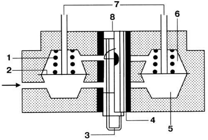 Pic. 2.102. The principle of operation of the dispenser-distributor of fuel.
1 - valve spring; 2 - diaphragm; 3 - dispenser plunger; 4 - slotted plunger sleeve; 5 - lower chamber; 6 - upper chamber; 7 - fuel supply to the nozzles; 8 - the control edge of the plunger.
The injector fuel line fittings have adjusting screws. It is not allowed to change the factory setting. When the pressure disc is raised, the control spool of the dispenser moves accordingly, opening its control edges for fuel access to the upper chamber 6 of the differential discharge valves, separated from the lower chamber 5 by diaphragm 2. Fuel pressure and spring force acting on the upper surface of the diaphragm. are greater than the pressure on its lower surface. As a result, the diaphragm bends down and opens the fuel supply channels to the fuel injectors.
Fuel pressure control
Fuel pressure control (fig 2.103), built into the body of the dispenser-distributor. maintains the required pressure in the fuel line and determines the amount of fuel drained into the tank.
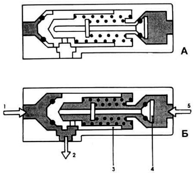 Pic. 2.103. The principle of operation of the fuel pressure regulator.
A - non-working position; B - working position.
1 - fuel supply from the fuel pump; 2 - fuel outlet to the tank; 3 - plunger of the fuel pressure regulator; 4 - uncoupling valve; 5 - control pressure supply.
This amount is adjusted by increasing or decreasing the number of spacers. installed under his body.
Pilot pressure regulator
Pilot pressure regulator (fig 2.104), mounted on the exhaust manifold. changes the amount of control pressure acting on the metering spool, depending on the engine temperature.
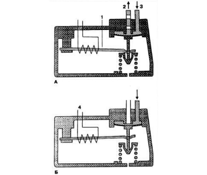 Pic. 2.104. The principle of operation of the control pressure regulator.
A - on a cold engine; B - on a hot engine.
1 - bimetallic spring; 2 - fuel drain; 3 - control pressure supply; 4 - winding of a bimetallic spring.
On a cold engine, the bimetallic spring 1 compresses the spring of the diaphragm valve, opening the fuel drain channel 2, which leads to a decrease in the resistance to the metering spool. A decrease in the control pressure at a constant air flow causes an increase in the stroke of the pressure disc. As a result, the metering spool is additionally raised. by increasing the amount of fuel supplied to the fuel injectors. As the engine warms up, the pressure of the bimetallic spring on the diaphragm valve spring decreases and the drain channel gradually closes. The control pressure reaches a normal value, and the enrichment of the combustible mixture stops.
Visitor comments