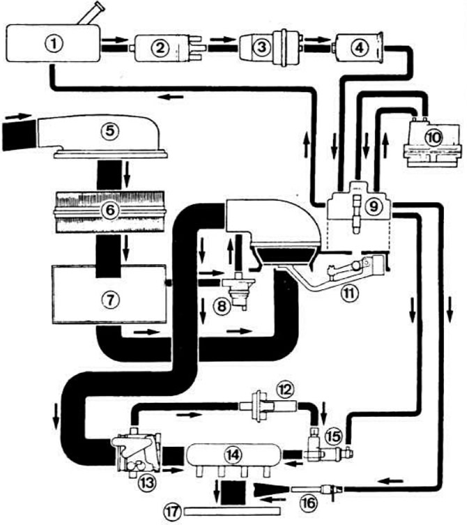
 Pic. 2.97. Structural diagram of the fuel injection system «K-Jetronic».
I - fuel tank; 2 - fuel pump; 3 - pressure accumulator; 4 - fuel filter; 5 - air intake; 6 - air filter; 7 - air filter housing; 8 - electromagnetic shut-off valve forced idling; 9 - fuel dispenser; 10 - control pressure regulator; 11 - pressure disk of the air flow meter; 12 - valve for additional air supply; 13 - throttle body; 14 - receiver; 15 - electromagnetic starting nozzle; 16 - fuel injector; 17 - inlet pipeline.
Thin lines indicate fuel lines, wide lines indicate air lines.
Further, the fuel through the filter 4 under pressure enters the fuel dispenser 9. Mounted on the movable lever between the air filter 6 and the throttle valve 13, the pressure disk 11 of the air flow meter is deflected depending on the vacuum in the intake pipe 17. The movement of the pressure disk of the air flow meter is transmitted on the control valve of the dispenser-distributor, determining the amount of fuel supplied to the engine cylinders and ensuring the optimal composition of the fuel-air mixture. The control pressure regulator 10 reduces the pressure on the control valve of the dispenser-distributor during engine warm-up, which causes an increase in fuel supply, i.e. enrichment of the combustible mixture. Additional air supply valve 12 installed in the air channel parallel to the throttle valve. brings additional air to the engine when starting and warming up a cold engine, which leads to an increase in the idle speed of the crankshaft. To facilitate the start of a cold engine, an electromagnetic starting nozzle 15 is provided. The opening time of which is determined by a time thermostat depending on the temperature of the coolant.
Adjustment data:
- idle speed of the crankshaft 750-850 rpm;
- carbon monoxide content (SO) in exhaust gases 1.0-1.5%;
- fuel pressure in the system 4.7-5.5 kgf/cm2:
- control pressure/at engine temperature,°C: 0.9 kgf/cm2 /10°C: 1.35 kgf/cm2 /20°C; 1.7 kgf/cm2 /30°С; 2.15 kgf/cm2 /40°С;
- control pressure on a hot engine 3.4-3.8 kgf/cm2;
- residual fuel pressure in the system: 2.5 kgf/cm2 10 minutes after the engine is stopped, 2.0 kgf/cm2 20 minutes later;
- injection start pressure 3.2-4.0 kgf/cm2.
Fuel tank
The fuel tank with a capacity of 48 liters is installed under the bottom of the body in its rear part. The fuel tank pipes have a larger diameter compared to the fuel tank pipes of cars with carbureted engines.
Visitor comments