Contents: Examination ↳ BEU ↳ Air flow meter ↳ Crankshaft Position/Speed Sensor ↳ Camshaft Position Sensor ↳ Coolant temperature sensor ↳ Intake Air Temperature Sensor ↳ Throttle potentiometer ↳ Vehicle speed sensor ↳ Power steering hydraulic pressure… ↳ Idle speed control valve ↳ Idle speed increase valve ↳ Troubleshooting ↳ Preliminary checks ↳ Reading fault codes ↳ Checking the ignition timing and… ↳ Basic ignition system check ↳ Basic fuel system check ↳ Checking the entire system ↳ Idle speed and mixture composition ↳
Warning: Before you begin, read the warning in paragraph 1 this chapter.
Note: This is an initial check of the fuel and air supply subsystems that are part of the engine management system. It is one of the preliminary checks of the entire engine management system (paragraph 3, chapter 6). It must be performed in conjunction with the fuel pump operation check (paragraph 8).
Examination
1. Check the tightness of all ground wire connections to the ground. Check all wires and electrical connectors that are connected to this system. Loose connections and poor ground contact can cause many defects that lead to more significant malfunctions.
2. Make sure the battery is fully charged. For accurate fuel dosing, the ECU and sensors must be supplied with the regulated voltage.
3. Check the air filter, if it is dirty or partially blocked, this can lead to poor engine performance and reduced fuel economy (see Chapter 1).
4. If you find a blown fuse, replace it and watch to see if it blows again. If it does, you should look for a short circuit in the wiring associated with this system (see Chapter 12).
5. Check the intake air duct - from the air intake to the intake manifold - for leaks, which can lead to an over-rich mixture. Also check the condition of the vacuum hoses connected to the intake manifold.
6. Disconnect the air duct from the throttle body. Inspect the throttle body for dirt, carbon or other deposits. If the throttle body is dirty, contact your dealer. Since the electronic control system is designed to compensate for things like deposits or dirt in the throttle body, it may be best to remove this dirt before it accumulates too much.
Note: A sticker on the housing warns that the housing bore and throttle valve are specially coated and should not be cleaned with carburetor cleaner.
7. With the engine running, place a screwdriver or stethoscope on each fuel injector in turn. Listen for clicks as the injectors operate.
8. If any of the fuel injectors does not work or the noise from it differs from the others, turn off the engine, disconnect the electrical connector of this injector. Measure the resistance between its terminals and compare the readings with the specified value (see Technical Data). If it differs from the specified value, replace the injector.
9. Rough idle. Deterioration in performance and/or increased fuel consumption can also be caused by clogged or dirty fuel injectors. Fuel additives, which can sometimes clean the injectors in such cases, are sold in auto parts stores.
10. The remaining system checks should be performed by dealers, since incorrect checks can damage the ECU. The engine management system has an electrical connector into which a special tester is plugged.
BEU
11. Do not attempt to check the ECU with any equipment. If you suspect that it is faulty, contact the dealers. Only if all other faults have been eliminated, should you conclude that the ECU is faulty and replace it.
Air flow meter
12. Its inspection must be carried out by specialists.
Crankshaft Position/Speed Sensor
13. Disconnect the sensor electrical connector.
14. Use an ohmmeter to measure the resistance between the sensor contacts. Compare the reading with the one specified in the Technical Requirements. If it differs from the one specified, replace the sensor.
15. Finally, connect the sensor electrical connector.
Camshaft Position Sensor
16. The procedure is similar to that described above - see paragraphs 13... 15.
Coolant temperature sensor
17. See Chapter 3.
Intake Air Temperature Sensor
18. Disconnect the sensor electrical connector.
19. Use an ohmmeter to measure the resistance between the sensor contacts. Depending on the temperature of the sensor tip, the measured resistance may differ, but it should be within the limits specified in the Technical Requirements. If the temperature of the sensor changes (when it is placed in the refrigerator for a while or when it is gently heated), its resistance should change accordingly.
20. If the measurements show that the sensor is faulty, replace it.
Throttle potentiometer
21. Remove the intake air duct chamber (where necessary, paragraph 4) and disconnect the potentiometer electrical connector.
22. Use an ohmmeter to measure the resistance between the contacts - first between the central and one of the two outer contacts, and then between the central and the other outer contact. The resistance should meet the Technical Requirements. When turning the throttle valve from fully closed (idle) to fully open, and back, the resistance should change smoothly.
23. If the measured resistance differs significantly from the specified value, or if a break in the circuit is detected or if the readings are unstable during operation of the damper, the potentiometer should be considered faulty and replaced.
Vehicle speed sensor
24. This sensor should be checked by dealers.
Power steering hydraulic pressure sensor
25. Disconnect the sensor electrical connector.
26. Use an ohmmeter to measure the resistance between the sensor terminals. When the engine is not rotating or idling, when the wheels are in the straight-ahead position, the resistance at the terminals should be close to zero. When the engine is running and the steering wheel is turned all the way, the pressure in the hydraulic system increases and the sensor contacts close. The ohmmeter should show infinite resistance.
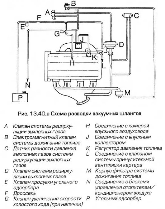
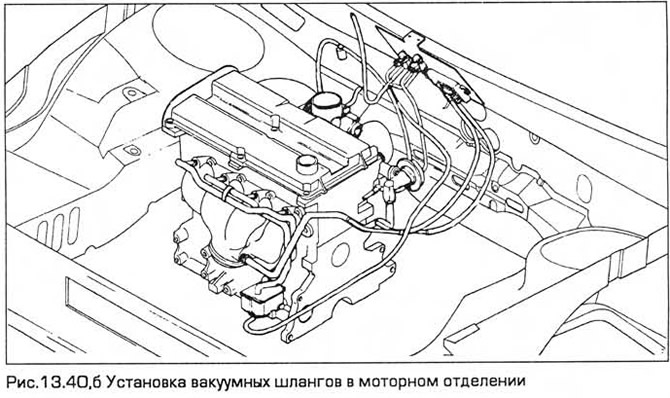
27. If the readings differ from those indicated above, the sensor is faulty and must be replaced.
Idle speed control valve
28. Where necessary, apply the parking brake, lift the front end and place it on supports.
29. Disconnect the electrical connector of the valve. Connect the terminals of the valve to the battery with a voltage of 12V: plus to terminal 37, and minus to terminal 21.
Caution: To avoid damaging the diode inside the valve, it is necessary to observe the polarity.
When the contacts close and open, a click should be heard. If it is not heard, measure the resistance between the terminals. If it corresponds to the specified value, the valve is normal, and the malfunction may be caused by the wiring or the ECU. If the resistance does not correspond to the specified value, replace the valve. Connect the valve connector.
Idle speed increase valve
30. Disconnect the electrical connector of the valve. Then apply voltage to its terminals directly from the battery. Make sure that when voltage is applied to the solenoid, the valve allows air flow, and when voltage is not applied to the solenoid, the valve is closed and air cannot pass through its channels. Another way to check is to connect an ohmmeter to the terminals of the valve and compare its readings with those specified in the Technical Requirements. If the valve is faulty, replace it.
31. The solenoid circuit diode is designed to smooth out voltage spikes that may occur when the solenoid is turned off. Therefore, a diode failure does not cause the valve to fail. If you suspect that the diode is still faulty, you can check it. To do this, disconnect the diode and check it with an ohmmeter. It should only pass current in one direction. If it passes current in both directions or in neither direction, then the diode is faulty and must be replaced.
Troubleshooting
32. The various components of the systems: fuel, ignition and emission control systems, are interconnected in such a way that diagnostics of a malfunction of any component by conventional methods is impossible.
33. To detect faults, the BEU has a self-diagnostic function, with the help of which faults in components are detected. If a fault occurs: the BEU identifies the fault, records the corresponding code in its memory and (in most cases) switches the faulty system to the operating mode with preset parameters stored in the memory. In this mode, the car can drive to the garage.
34. All possible faults are displayed using special equipment as a three-digit digital code (EEC-IV) or as a message (EEC-V). When the device is connected to the diagnostic equipment via the diagnostic connector, it displays information about the fault.
35. Below is a troubleshooting procedure. After reading it, decide, based on your experience and available equipment, whether it is worth doing it yourself. But even if you do not perform the troubleshooting procedure, it is not difficult to perform preliminary checks. To do this, you need to take into account the information paragraph 1, follow the instructions exactly. The sequence of checks:
- a) Perform preliminary checks (see below).
- b) Read the fault code*.
- c) Check the ignition timing and basic idle speed. Repeat the trouble code check to see if the fault is corrected*.
- d) Perform a basic check of the ignition system components. Repeat the code check to see if the fault is corrected or not*.
- d) Perform a basic check of the fuel system components. Repeat the trouble code check to see if the fault is corrected or not*.
- e) If the fault persists, perform a full system check*.
Note: An asterisk indicates procedures that require special diagnostic equipment.
Preliminary checks
Note: When performing troubleshooting checks, remember that if the fault occurs almost immediately after maintenance or repair, it should be looked for in the area of this maintenance. The fault may be caused by improperly installed components.
36. If you are looking for the cause of a "partial" engine failure, such as incomplete implementation of its characteristics, then in addition to the checks described below, check the compression in the cylinders (Chapter 2A or 2B) and also take into account that a faulty hydraulic compensator can adversely affect the valve clearance. Make sure that the fuel filter is replaced in accordance with the maintenance schedule.
37. If the system is completely inactive, remember that this may be caused by the alarm system.
38. First of all, turn on the ignition and listen to the fuel pump. The sound of the electric motor should be heard from under the rear seats. Provided that there is enough fuel in the tank, the pump should start and run for one or two seconds, and then turn off. This should happen every time the ignition is turned on. If the pump runs all the time while the ignition is on, then the electronic control system is operating in the "limp home" mode. This almost certainly indicates a malfunction of the ECU itself. and therefore the car should be presented to the dealers for inspection. In this case, do not try to test the system yourself.
39. If the pump is working normally (or not working at all), then the following checks should be performed.
40. Using the diagram and sequentially inspecting the vacuum hoses and pipes located in the engine compartment, make sure that they are correctly laid and securely fastened, have no cracks or other damage causing leaks, and do not have kinks that reduce the internal cross-section (see Fig. 13.40, a, b). Inspect all hose connections and replace damaged or deformed hoses.
41. Inspect the fuel lines, starting from the fuel tank in the direction of the filter to the fuel line (pressure and drain lines). Replace sections that have leaks or damage.
42. Make sure the accelerator cable is securely fastened and adjusted. If you are not sure, replace the cable (see chapter 4).
43. If you suspect that the throttle valve is not working properly, remove the air intake plenum from the throttle body. Check that the valve moves easily and smoothly throughout its travel, from fully closed to fully open and back, while your assistant presses the accelerator pedal. If the throttle valve does not move smoothly (and the accelerator cable has been checked and is in good condition), lubricate the throttle linkage with penetrating oil and recheck after a while.
44. Start the engine and let it idle. Check the air intake duct for leaks, starting at the air intake on the inner fender panel. Leaks are usually indicated by a whistling sound. Small leaks can be detected by spraying soapy water on the appropriate joints. The leak will be indicated by the appearance of an air bubble or by the suction of liquid (depending on the pressure at that location). If a leak is detected, tighten the appropriate clamp and/or replace the faulty component.
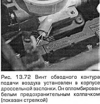
45. Similarly, check the exhaust system for leaks (paragraph 15).
46. Electrical connections can be checked by wiggling each connector one at a time while the engine is idling. A faulty connector should be replaced. Note that this may require replacing a section of the wiring harness entirely.
47. Turn off the engine. If the fault is still not detected, check the ignition voltage using an analyzer with an oscilloscope. If you do not have such a device, you can only check the connection and resistance of the high-voltage wire of each spark plug by removing it one by one, and also check the connections and resistance in the ignition coil. See. chapters 1 and 5B.
48. The final operation of the preliminary checks is to check the level of carbon monoxide in the exhaust pipe using a gas analyzer. This operation cannot be performed without special control equipment.
Reading fault codes
Note: The remainder of this section covers procedures specific to the EC-IV Fuel Injection System (pre-08/96 models). The EC-IV and EC-V Fuel Injection Systems (later models) require the Ford 2000 Fault Reader, which directly displays the fault without reference to the fault code.
49. The checks described above help to eliminate most engine management system faults. If the fault still persists, connect the fault reader to the BZU.
50. A fault code reader is a portable electronic device that receives information stored in the memory of the BZU and converts it into codes displayed on the display as two- or three-digit numbers. The most advanced versions of these devices also allow for the monitoring of sensors and actuators. Some of these devices allow for the storage of information, for example, during a test drive, and subsequently display of the faults recorded during the test.
51. To check the EC-IV fuel injection system, Ford recommends using the STAR reader. This fault reader is used by most dealers.
52. Since fault reading devices differ from each other, it is impossible to give an exact description of the entire sequence of tests. Therefore, it is necessary to follow the instructions of the manufacturer of such a device in accordance with the table of codes presented below. The following ten points describe the procedure for reading codes with the Ford-STAR tester.
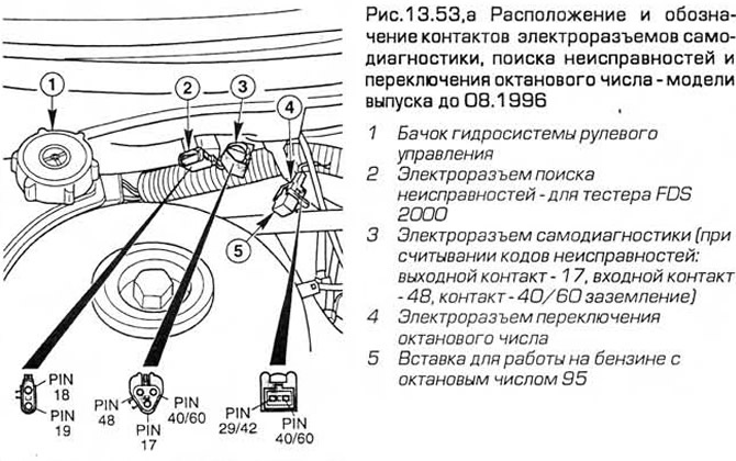
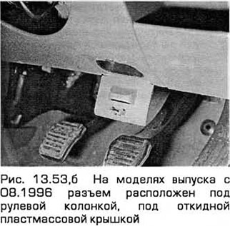
53. Before performing the procedure, apply the parking brake, turn off the air conditioner and other electrical consumers (lights, rear window heater, etc.). Set the transmission to neutral (non-automatic transmissions) or select the "P" position (automatic transmissions). If you need to check a rotating engine, it must be fully warmed up to normal operating temperature. Using adapters, connect the tester to the diagnostic connector of the system. On models manufactured before 08.1996, this is a triangular, three-pin connector located on the right side of the engine compartment bulkhead. On later models, the connector is located under the steering column, under the hinged plastic cover (see Fig. 13.53, a-c).
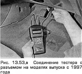
Warning: For later models, use the FDS2000 reader. The STAR tester is not suitable for them.
If using a voltmeter, connect its positive lead to the positive battery terminal and its negative lead to the diagnostic connector socket 17. Have paper and pencil handy to write down the codes.
54. Set the reader to the operating mode. The Ford-STAR reader will perform a display test and you will need to enter the test mode parameters. The first step of the test is performed with the ignition on and the engine not rotating. When you press the "MEM/TEST" button, the display shows "TEST" and the readiness code "000". Then the command code "010" appears. The accelerator pedal must be pressed within 10 seconds of this code being displayed, otherwise the tester will subsequently display faults corresponding to codes "576" or "577".
55. After this, the tester displays the fault codes, each code is repeated again. If there are no faults, the code "111" is displayed.
56. The tester then displays the code "010" (used as a separator), followed by the codes of the faults stored in the BZU memory. If there are no faults, the code "111" is displayed.
57. When working with the tester, the operator should now fully depress the accelerator pedal. The tester will check the actuators. The algorithm of subsequent testing includes the function of "shake test", during which the operator can check the various electrical connectors as indicated above (in this case, any malfunction will be registered and the corresponding code will be displayed), the function of recalling the displayed codes and the function of clearing the memory of the BZU at the end of the test, when all the malfunctions have been identified.
58. The next step when using the Ford-STAR tester is to test the rotating engine. After setting the tester to the operating mode (see item 53), start the engine and bring it to idle mode. When you press the "MEM/TEST" button, the inscription "TEST" appears, followed by one of the two codes listed below.
59. If the warning code "998" appears followed by the appropriate fault code, turn the ignition off and check (as directed by the display) the coolant temperature sensor, intake air temperature sensor, mass air flow meter, throttle potentiometer and/or their associated circuits. Then repeat the test.
60. If the code "020" appears, perform the following procedures within ten seconds:
- a) Depress the brake pedal fully.
- b) Turn the steering wheel to the stop (in any direction), and then return it to the middle position to generate a signal from the steering hydraulic pressure sensor. If such a signal is not generated, the code "52 G" appears.
- c) On models with automatic transmission, press and release the high gear release button, then press and release the ECO/Sport mode switch.
- d) Wait until the code "010" - separator appears. Then within ten seconds fully depress the accelerator pedal, quickly increasing the engine speed above 3000 rpm and release the pedal.
61. Malfunctions detected by the system are recorded and displayed on the display. Each code is repeated one more time. If there are no malfunctions, the code "111" appears.
62. After displaying the codes of all registered faults, the ECU starts its program ("maintenance setup program"):
- a) The program operates for two minutes.
- b) The idle speed control valve is deactivated and a pre-programmed (non-adjustable) value is entered for the idle speed. If the appropriate equipment is connected, the basic idle speed can be checked (but it is not adjustable).
- c) The ignition timing can be checked by connecting a stroboscope (but it is also not adjustable).
- d) Fully depress the accelerator pedal while performing the cylinder differential pressure test. This will turn off each fuel injector in turn and register a corresponding decrease in engine speed. If the test is successful, the code "090" will be displayed.
- d) After two minutes the program will terminate. This will be noticeable by a brief increase in RPM followed by a return to normal idle speed when the idle speed control valve is reactivated.
63. As with the non-rotating engine test, the subsequent testing includes a "shake test" function during which you can check the various electrical connectors as described in item 53. (in this case, any fault will be registered and the corresponding code will be displayed), a function for recalling the displayed codes and a function for clearing the ECU memory at the end of the test when all faults have been identified. If you are using equipment other than the Ford-STAR reader, the ECU memory can be cleared by disconnecting the battery. If this is not done, the codes stored in it will appear together with the codes stored subsequently. However, note that disconnecting the battery affects other circuits with a memory function (such as the clock and audio unit). If it is necessary to disconnect the battery to service other parts of the vehicle, first check whether any fault codes are stored.
64. Below is a table with error codes. It also provides a decoding of the codes and the actions to be taken if the codes are displayed.
| Code | Meaning | Action |
| 000 | Ready for testing | - |
| 010 | Command code/code separator | Press the accelerator pedal fully and then release it |
| 020 | Command code | Fully depress and then release the brake pedal |
| 10 | Low pressure in cylinder #1 | When checking the pressure difference in the cylinders |
| 20 | Low pressure in cylinder #2 | When checking the pressure difference in the cylinders |
| 30 | Low pressure in cylinder #3 | When checking the pressure difference in the cylinders |
| 40 | Low pressure 8 cylinder. No.4 | When checking the pressure difference in the cylinders |
| 90 | Checking the difference in pressure in the cylinders - normal | - |
| 111 | No faults found | - |
| 112...114 | Intake Air Temperature Sensor | Check the component (see above) |
| 116...118 | Coolant temperature sensor - engine not warmed up to normal operating temperature. | If the fault persists at normal operating temperature, check the component (Chapter 3) |
| 121...125 | Throttle potentiometer | Check the component (see above) |
| 129 | Incorrect air flow signal when performing a check | Repeat the check |
| 136,137 | Oxygen sensor | Check the component (Chapter 4B) |
| 139 | Oxygen sensor | Check the component (Chapter 4B) |
| 144 | Oxygen sensor | Check the component (Chapter 4B) |
| 157...159 | Air flow meter | Check the component (see above) |
| 167 | Incorrect signal of potential throttle during test execution | Repeat the check |
| 171 | Oxygen sensor | Check the component (Chapter 4B) |
| 172 | Oxygen sensor - mixture too lean | Check the component (Chapter 4B) |
| 173 | Oxygen sensor - too rich mixture | Check the component (Chapter 4B) |
| 174,175 | Oxygen sensor | Check the component (Chapter 4B) |
| 176 | Oxygen sensor - mixture too lean | Check the component (Chapter 4B) |
| 177 | Oxygen sensor - too rich mixture | Check the component (Chapter 4B) |
| 178 | Oxygen sensor | Check the component (Chapter 4B) |
| 179 | Fuel system - mixture too lean | Check the EGR valve (Chapter 4B) |
| 181 | Fuel system - over-enriched mixture | Check the EGR valve (Chapter 4B) |
| 182 | Idle speed - mixture too lean | Check idle speed control valve (see above) |
| 183 | Idle - over-rich mixture | If the mixture composition is normal, check the fuel system (see below) |
| 184,185 | Air flow meter | Check the component (see above) |
| 186 | Fuel injector opening interval is too long | Check the system (see below) |
| 187 | Fuel injector opening interval is too small | Check the system (see below) |
| 188 | Oxygen sensor - mixture too lean | Check the component (Chapter 4B) |
| 189 | Oxygen sensor - too rich mixture | Check the component (Chapter 4B) |
| 191 | Idle - mixture too lean | Check the EGR valve (Chapter 4B) and the idle speed control valve (see above) |
| 192 | Idle speed - over-rich mixture | Check the EGR valve and the idle speed control valve (Chapter 4B) |
| 194.195 | Oxygen sensor | Check the component (Chapter 4B) |
| 211 | Ignition signal is not received by the ECU | Check the system (see below) |
| 212 | Tachometer chain | Check the system (see below) |
| 213 | Ignition signal is not received from the ECU | Check the system (see below) |
| 214 | Camshaft Position Sensor | Check the component (see above) |
| 215...217 | Ignition coil | Check the system (see below) |
| 218,222 | Tachometer chain | Check the system (see below) |
| 226 | Signal from the ECU/ignition module | Check the system (see below) |
| 227 | Crankshaft position sensor | Check the component (see above) |
| 228 | Ignition module/coil 1 winding | Check the system (see below) |
| 229 | Ignition module/coil 2 | Check the system (see below) |
| 231 | Ignition module/coil 3 | Check the system (see below) |
| 232 | Primary windings of the ignition coil | Check the system (see below) |
| 233 | Ignition module | Check the system (see below) |
| 234...237 | Primary windings of the ignition coil | |
| 238 | Ignition module/ignition coil primary windings | Check the system (see below) |
| 239 | Ignition signal does not reach the ECU when the engine is running | Check the system (see below) |
| 241 | Incorrect signal from the ECU and/or ignition module when performing a check | Repeat the check |
| 243 | Ignition coil failure | Check the system (see below) |
| 311...316 | Fuel afterburning system | Check the system (see below) |
| 326 | Exhaust gas differential pressure sensor in the EGR system | Check the component (Chapter 4B) |
| 327 | Exhaust gas pressure difference sensor or electromagnetic valve in the EGR system | Check the component (Chapter 4B) |
| 328 | Electromagnetic valve of the EGR system | Check the component (Chapter 4B) |
| 332 | The EGR valve does not open | Check the component (Chapter 4B) |
| 334 | Electromagnetic valve of the EGR system | Check the component (Chapter 4B) |
| 335 | Exhaust gas differential pressure sensor in the EGR system | Check the component (Chapter 4B) |
| 336 | Exhaust gas pressure too high | Check the component (Chapter 4B) |
| 337 | Exhaust gas differential pressure sensor or electromagnetic valve in the EGR system | Check the component (Chapter 4B) |
| 338,339 | Temperature sensor, coolant | Check the system (see below) |
| 341 | The service connector is grounded | Disconnect the connector, repeat the test and connect the connector |
| 411 | Engine speed is too low during testing | Check for air leaks, then recheck |
| 412 | Engine speed is too high during testing | Check for air leaks, then recheck |
| 413...416 | Speed control valve | Check the component (see above) of the idle speed |
| 452 | Engine speed sensor | Check the component (chapter 6 paragraph 4) |
| 511,512 | Memory unit of the electronic control unit | Check if the battery is disconnected, then check fuse 11, if the fault persists, replace the ECU (par. 14) |
| 513 | BEU reference voltage | Check the system (see below) |
| 519,521 | The steering hydraulic pressure sensor does not respond when tested | Make sure the component is installed and connected, then retest, if the fault persists, check the whole system (see below) |
| 522,523 | Selector position sensor | Check the component (Chapter 7B) |
| 536 | Brake pedal microswitch does not operate when tested | Repeat the check |
| 538 | Operator error during verification | Repeat the check |
| 539 | During the test, the air conditioner turns on | Turn off and repeat the test |
| 542.543 | Fuel pump chain | Check the system (see below) |
| 551 | Idle Speed Control Valve Circuit | Check the system (see below) |
| 552 | Fuel afterburning system | Check the system (see below) |
| 556 | Fuel pump chain | Check fuel pump relay, if fault persists, check system (see below) |
| 558 | EGR system solenoid valve circuit | Check the system (see below) |
| 563 | Radiator Fan Relay and/or Circuit (High Speed Mode) | Check the system (see below) |
| 564 | Radiator Fan Circuit and/or Circuit | Check the system (see below) |
| 565 | Carbon adsorber solenoid valve | Check the component (Chapter 4B) |
| 573 | Radiator Fan Relay and/or Circuit | Check the system (see below) |
| 574 | Radiator Electric Fan (High Speed Mode) Relay and/or Circuit | Check the system (see below) |
| 575 | Fuel cut-off switch and/or fuel pump circuits | Check the system (see below) |
| 576,577 | When checking, the accelerator pedal is not fully depressed - the automatic transmission downshift device does not work | Repeat the check |
| 621 | Automatic Transmission Shift Solenoid 1 Circuit | see chapter 7B |
| 622 | Automatic Transmission Shift Solenoid 2 Circuit | see chapter 7B |
| 624 | Automatic Transmission Pressure Control Solenoid | see chapter 7B |
| 625 | Automatic Transmission Pressure Control Solenoid Circuit | see chapter 7B |
| 629 | Automatic Transmission Torque Converter Solenoid | see chapter 7B |
| 634 | Selector Position Sensor Circuit | Check the component (Chapter 7B) |
| 635,637 | Automatic Transmission Fluid Temperature Sensor | see chapter 7B |
| 639 | Automatic transmission speed sensor | see chapter 7B |
| 645 | 1st gear automatic transmission | see chapter 7B |
| 646 | 2nd gear automatic transmission | see chapter 7B |
| 647 | 3rd gear automatic transmission | see chapter 7B |
| 648 | 4th gear automatic transmission | see chapter 7B |
| 653 | Automatic transmission high gear release button and Economy/Sport mode switch do not engage when tested | Repeat the check |
| 998 | Warning code | Check for faults indicated by the following codes |
Checking the ignition timing and base idle speed
Note: Both parameters are controlled by the ECU. The ignition timing is not adjustable at all. The basic idle speed is set at the factory and cannot be changed.
65. If after reading the fault codes (and performing the corresponding checks) the fault is not eliminated, then the next step is to check the control via the BZU of the two above-mentioned parameters. For this, you need a Ford-STAR tester, as well as an accurate tachometer and a high-quality stroboscope. Without this equipment, the check cannot be performed.
66. Before performing the procedure, apply the parking brake, turn off the air conditioner and other electrical consumers (lights, rear window heater, etc.). Set the transmission to neutral (non-automatic transmissions) or select the "P" position (automatic transmissions). Start the engine and wait until it warms up to normal operating temperature. When performing the test, the radiator fan should rotate constantly. The tester will notify the ECU that it is on.
67. Raise the front end and support it securely. Remove the accessory belt cover (Chapter 1). Touch up the two pairs of marks on the inner and outer rims of the crankshaft pulley with white paint. Note that there are no reference marks on the pulley that correspond to the ignition timing setting. In the case of clockwise crankshaft rotation, the first pair of marks is not used for the vehicles presented in this manual. The second pair of marks indicates TDC when it is aligned with the rear edge of the raised mark on the oil pan. When checking the ignition timing setting, the rear edge of the mark on the oil pan should be located directly in front of the TDC marks.
68. Start the engine and bring it to idle speed. Perform the test with the engine running until the moment when the ECU enters the "settings during maintenance" program.
69. Using a stroboscope, check the alignment of the marks, as indicated above, at idle speed. If the marks do not align as indicated, then there may be a fault in the system and to identify it, you need to check the entire system (see below).
70. Use a tachometer to check the base idle speed and compare it with the specifications.
71. If the speed reading differs significantly from the specified value, check for air leaks (preliminary checks, see above) or other faults that may be causing this.
72. The basic idle speed is set at the factory by the air bypass screw (mounted in the right front corner of the throttle body). This screw controls the amount of air passing through the bypass circuit to bypass the throttle valve when it is fully closed in the idle position. This screw is sealed with a safety cap (see Fig. 13.72). During maintenance, the idle speed is controlled by the ECU. The ECU has the ability to compensate for factors that may require changing the idle speed - such as engine wear, dirt deposits in the throttle body, etc. Therefore, the position of this screw must not be changed. If its position has been changed, a blue safety cap must be installed on the screw and the engine must be brought to idle mode and kept there for at least five minutes so that the ECU enters the idle parameters in the learning mode.
73. After completing both tests and finishing the "service adjustments" program, follow the instructions in the tester manual and see if the fault has been corrected.
Basic ignition system check
74. If the fault is not corrected after the previous checks, the next step is a basic check of the ignition system components using an analyzer with an oscilloscope. If you do not have such equipment, you can check only the connections and resistance of the spark plug wires and the connections and resistance of the ignition coil, removing each spark plug in turn. See. chapters 1 and 5B.
Basic fuel system check
75. If the fault is not corrected as a result of the previous checks, proceed to the next step - a basic check of the fuel system components.
76. Provided that the fuel pump is working properly (according to the results of preliminary checks), the fuel filter is not clogged and there are no leaks in the system, the next step is to check the fuel pressure (paragraph 7). If it is normal, check the fuel injectors (see above in this paragraph) and the positive crankcase ventilation system (chapter 1).
Checking the entire system
77. The final step in the testing procedure is to test the entire system using a special device that is connected between the ECU and its electrical connector. In this case, the specific circuits that the fault codes indicate can be tested while connected to the system and, if necessary, with the engine running. In this case, the output signal of many system components can be measured for a more thorough check.
78. In addition to such a device and adapters, special elements are required for this check. Such a check should be performed by dealers.
Idle speed and mixture composition
79 These parameters are not adjusted manually, they are controlled by the ECU. The parameter settings can only be checked using special diagnostic equipment.
80. If you suspect that these parameters are not normal, contact your dealer to check the entire system.
81. On models with a heated windshield, an idle speed increase valve is installed. It increases the speed to compensate for the increased load on the engine when the heater is turned on. When the valve is open, air from the intake air duct chamber bypasses the throttle valve and the idle speed control valve, and goes directly into the intake manifold through a connection on its left edge. Once this system is turned on, it only operates for four minutes while the heater circuit is powered. The ECU controls it in addition to the main idle speed control.
This article is a copy from the website fordbook