Attention! Before you begin, read the caution in paragraph 1 of this chapter.
Electronic control unit
Warning: BEU is a fragile device. It must not be dropped, shaken or knocked on it, it must also be protected from moisture and sudden changes in temperature. Do not touch the connector pins, as they may contain static charge, which, if shorted, will damage the electronic parts inside the ECU.
Note: When replacing the EEC-V fuel injection control system, be aware that it must be programmed for your engine using the FDS 8000 special equipment. If this is not done, the system will remain in the "limited controllability" and the engine will not realize its potential for power and economy.
Withdrawal
1. Disconnect the negative battery cable (chapter 5A).
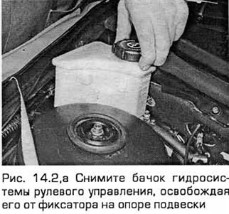
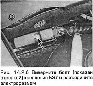
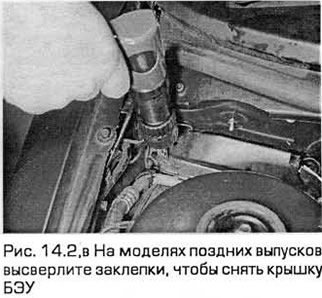
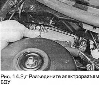
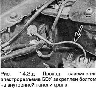
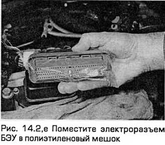
2. Carefully remove the steering fluid reservoir by lifting and releasing it from the retainer on the suspension support. Unscrew the BEU mounting bolt and disconnect the electrical connector (see fig. 14.2, a-e).
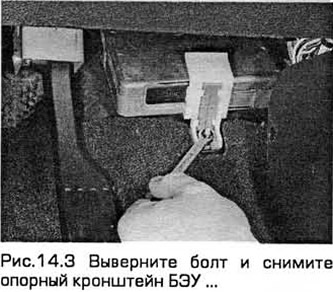
3. From inside the passenger compartment, unscrew the bolt and remove the support bracket (see fig. 14.3).
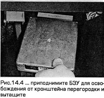
4. Then lift the ECU to release it from the bulkhead bracket and pull out the assembly (see fig. 14.4).
Installation
5. Installation - in the reverse order of removal. In any case, when the battery is disconnected, the parameters relating to the idle speed control, as well as other operating parameters, must be re-entered into the electronic memory of the control device. The BEU performs the input of such parameters on its own, but before they are entered, the engine may experience starvation, interruptions or unstable idling or not achieve its characteristics. To enter these parameters into the BEU in the learning mode, start the engine and bring it to the operating mode at a speed that has minimal differences from the idle speed. Keep it in this mode until it warms up to normal operating temperature, and then let it run at 1200 rpm for about two minutes. After that, you need to make a trip to the distance that you require. When you have driven about eight km using the various driving modes, the learning process is complete.
Air mass meter
Withdrawal
6. Disconnect the negative battery cable (chapter 5A).
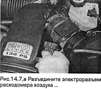
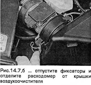
7. On models with 4-cylinder engines, disconnect the electrical connector, releasing it from the retainer. Release the clips and remove the air cleaner cover. Then release the two small latches and separate the flowmeter from the cover. Release the clamp securing the flow meter to the resonator hose and remove the flow meter (see Fig.14.7, a, b).
8. On models with V-shaped 6-cylinder engines, remove the air cleaner (paragraph 4). Turn out bolts of a flowmeter and remove it from a cover of an air cleaner.
Installation
9. Installation - in the reverse order of removal. The flow meter and air cleaner cover must be properly installed and securely fastened. to prevent air leaks.
Crankshaft Position/Speed Sensor
Withdrawal
10. Disconnect the negative battery cable (chapter 5A).
11. Apply the parking brake. Raise the front end and place it on stands.
12. On models with 4-cylinder engines, remove the locker of the front left wheel arch. On models with V-shaped 6-cylinder engines, remove the locker of the front right wheel arch.
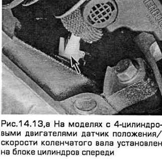
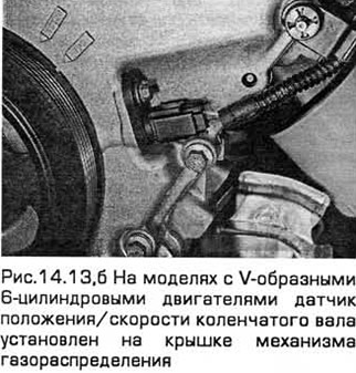
13. Disconnect the wiring from the sensor (see fig.14.13.a,b).
14. Turn out screws and remove the gauge.
Installation
15. Installation - in the reverse order of removal.
Camshaft position sensor
Withdrawal
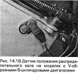
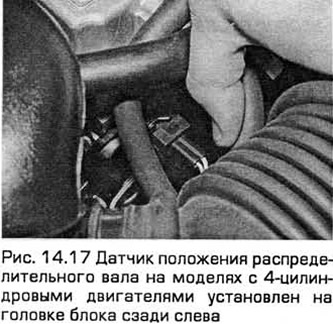
16. On models with 4-cylinder engines, the sensor is installed on the head of the block at the rear left. On models with V-shaped 6-cylinder engines, the sensor is installed on the timing cover on the right (see fig. 14.16).
17. To access the sensor, remove the air mass meter and (on models with 4-cylinder engines) resonator (see fig.14.17). Release the fuel injection and drain lines from the clamps.
18. Disconnect the electrical connector of the sensor, releasing its retainer. Remove the screw and remove the sensor from the block head. Note that some oil may leak from the sensor.
Installation
19. Installation - in the reverse order of removal, taking into account the following:
- A) Lubricate the O-ring with petroleum jelly or clean engine oil (round section) sensor.
- b) Install the sensor in the head of the block and remove excess grease. Then tighten it.
- V) Tighten the screw to the required torque.
Coolant temperature sensor
20. see chapter 3.
Intake air temperature sensor
Withdrawal
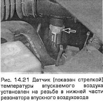
21. To access the sensor, remove the air mass meter and (on models with 4-cylinder engines) resonator (see fig.14.21).
22. Disconnect the electrical connector of the sensor, releasing it from the retainer. Then, unscrew the sensor from the resonator, intake duct, or air cleaner housing.
Installation
23. Installation - in the reverse order of removal. Tighten the transducer to the correct torque, being careful not to overtighten the transducer as its tapered threads may damage the component into which the transducer is screwed.
Throttle Potentiometer
Withdrawal
24. On models with 4-cylinder engines, remove the intake air duct chamber (paragraph 4). On V-6 models, remove the coolant pump pulley shield. If necessary, remove the positive crankcase ventilation hose from the air intake duct.
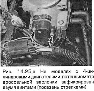
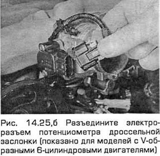
25. Disconnect the potentiometer electrical connector, releasing the connector lock. Remove the mounting screws and remove the assembly from the throttle body (see Fig. 14.25, a, b). Do not turn the potentiometer knob beyond its normal stroke to avoid damaging the assembly.
Installation
26. Installation - in the reverse order of removal, taking into account the following:
- A) Align the potentiometer slider with the throttle shaft (with damper closed) and align the potentiometer housing so that the screws fit freely into the throttle body.
- b) Tighten the screws evenly without overtightening them so as not to damage the potentiometer body.
Speedometer sensor
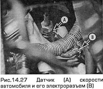
27. On models prior to 1997, this sensor is installed on the base of the speedometer drive cable and is removed together with the speedometer drive gear (see fig.14.27). On models of later releases, it is installed in the same place, but the cable is missing due to the use of an electronic speedometer. See chapter 7A or 7B.
Steering hydraulic pressure sensor
Withdrawal
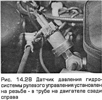
28. Disconnect the electrical connector of the sensor, releasing it from the retainer. Then unscrew the sensor (see fig. 14.28).
29. Before removal, cover the sensor with rags to catch smudges. If a sealing washer is installed under the sensor, inspect it for wear or damage and replace if necessary.
Installation
30. Installation - in the reverse order of removal. Tighten the sensor securely. Then refill the tank (Chapter 1) to compensate for leaks from the system and bleed air through the valve (see chapter 10).
Throttle body (models with 4-cylinder engines)
Withdrawal
31. Disconnect the negative battery cable (chapter 5 paragraph 1).
32. Remove the intake duct chamber (paragraph 4).
33. Disconnect the accelerator cable from the throttle linkage. Disconnect the cruise control actuator cable (if available) (see chapter 12).
34. Disconnect the large electrical connector (closest to the fuel pressure regulator), releasing its wire lock. In the same way, disconnect the electrical connector, throttle potentiometer.
35. Tag and then disconnect all vacuum hoses from the throttle body.
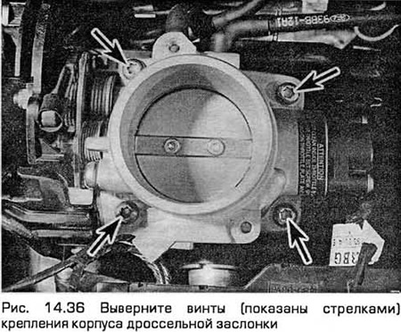
36. Remove the screws securing the throttle body (see fig. 14.36). Then disconnect the housing and gasket from the intake manifold. Discard the gasket. Once removed, it must always be replaced.
37. Using a soft brush and flushing agent, carefully clean the outer surface of the throttle body, and then blow out all channels with compressed air.
Caution: Do not clean the throttle body bore, throttle body or throttle potentiometer with solvent or a scraper, but wipe thoroughly with a soft, clean cloth.
Installation
38. Installation - in the reverse order of removal. Install a new gasket and tighten the housing screws to the correct torque.
Throttle body (models with V-shaped 6-cylinder engines)
Withdrawal
39. Disconnect the negative battery cable (chapter 5 paragraph 1).
40. Remove the air cleaner and intake duct (paragraph 4). Remove the coolant pump pulley shield as well.
41. Disconnect the throttle potentiometer electrical connector and disconnect the wiring from the rod. Move the wiring to the side.
42. Disconnect the accelerator cable from the throttle linkage. Disconnect the cruise control actuator cable (if available) (see chapter 12).
43. Turn out bolts and a nut of fastening of the throttle body. Then remove the housing and gasket from the intake manifold. Discard the gasket. Once removed, it must always be replaced.
44. Using a soft brush and flushing agent, carefully clean the outer surface of the throttle body, and then blow out all channels with compressed air.
Caution: Do not clean the throttle body bore, throttle body or throttle potentiometer with solvent or a scraper, but wipe thoroughly with a soft, clean cloth.
Installation
45. Installation - in the reverse order of removal. Install a new gasket and tighten the body bolts and nut to the correct torque.
Fuel rail and fuel injectors (models with 4-cylinder engines)
Withdrawal
Note: For simplicity, and to ensure the utmost cleanliness of reassembly, this procedure involves removing the fuel rail assembly along with the fuel injectors and pressure regulator. The fuel injectors can then be serviced individually on a clean work surface.
The fuel injectors can also be removed and installed individually once you depressurize the fuel system and disconnect the battery.
46. Relieve residual pressure in the fuel system (paragraph 2) and equalize the pressure in the tank by removing the tank cap.
Warning: Be aware that fuel remains in system components when residual pressure is released and take precautions before disconnecting them.
47. Disconnect the negative battery cable (chapter 5 paragraph 1).
48. Remove the intake duct chamber (paragraph 4),
49. To improve access, you can disconnect the accelerator cable from the throttle linkage. Disconnect also the cruise control actuator cable (chapter 12) (if available).
50. Disconnect the four electrical connectors of the fuel injectors, releasing them from the wire clamps. On models from 07.1997, the wiring harness is routed in a groove.
51 Disconnect the pressure and drain lines by disconnecting the quick couplers near the brake booster. Then detach the fuel hoses from the intake manifold. Use a rag to remove fuel spills (see fig.14.51).
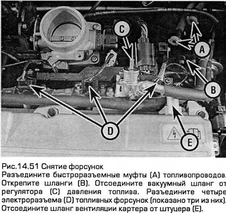
Note: Do not disconnect the threaded couplings installed on the fuel line fittings unless absolutely necessary. They are sealed at the time of manufacture. To perform maintenance, it is sufficient to use quick couplings.
52. Disconnect the crankcase ventilation hose from the fitting on the head cover (on production models up to 07.1997) and a vacuum hose from the fuel pressure regulator.
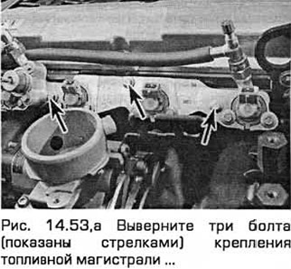
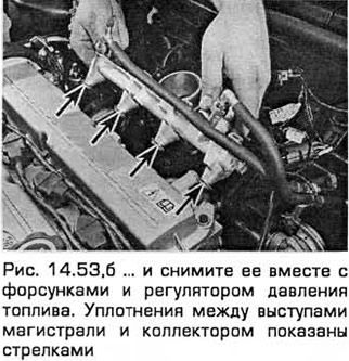
53. Remove the three bolts securing the fuel line and remove it, carefully separating it from the intake manifold so that the remaining fuel is glassed into a clean container (see fig. 14.53, a, b). Please note that on production models from 07.1997, the design of the fuel line has been changed, and the injectors are installed directly in the intake manifold. Pay attention to the seals between the protrusions of the line and the manifold. After removing the line, they must always be replaced.
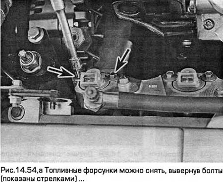
54. Carefully secure the line in a vise with soft jaws. On models prior to 07.1997, remove the two mounting bolts on each fuel injector and remove the injectors. On models of later releases, pull the clamps and pull the nozzles out of the line. Place each nozzle in a clean container labeled (see Fig. 14.54, a, b).
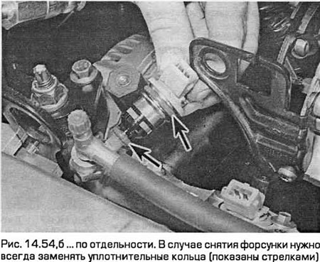
55. If you will replace the nozzle (And), discard the old nozzle, line lug seal, and O-rings. If you are only replacing the injector o-rings because they are leaking and reinstalling the same injector in its place, remove the old line lug seal as well and discard it.
56. Subsequent operations for checking fuel injectors are beyond the power of the car owner. If you doubt the correctness of the injector (OK), check with dealers.
Installation
57. Installation - in the reverse order of removal, taking into account the following:
- A) Lubricate the seal on each line lug and O-ring with clean engine oil.
- b) On production models up to 07.1997, install each injector into the line recess as follows. so that the mounting lug on the nozzle head fits into the slot in the line. Tighten the bolts to the required torque.
- V) Dock and fix the quick couplings of the injection and drain fuel lines (paragraph 3).
- G) Secure the ventilation hose, vacuum hose and wiring with the necessary clamps and ties, routing them appropriately.
- d) Finally, turn the ignition on and off five times. to start the fuel pump and restore pressure in the system (without cranking the engine). Before starting the engine, check for fuel leaks in the area of the connections that you disassembled.
Fuel line and fuel injectors (models with V-shaped 6-cylinder engines)
Withdrawal
58. Eliminate residual pressure in the fuel system (paragraph 2) and equalize the pressure in the tank by removing the tank cap.
59. Disconnect the negative battery cable (chapter 5 paragraph 1).
60. Remove the top section of the intake manifold (chapter 2B).
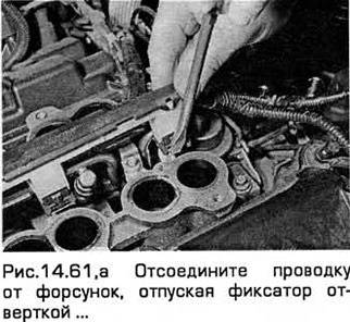
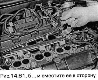
61. Disconnect the wiring from the injectors and move it to the side (see fig. 14.61, a, b).
Release models up to 07.1997
62. The injectors can be removed by first unscrewing the clamp bolts and removing the clamps. Place each nozzle in a clean, labeled container. The injectors can also be removed along with the fuel line.
63. To remove the line, release the clamps and disconnect the fuel hoses from the line. Disconnect the vacuum hose from the fuel pressure regulator as well. Then turn out bolts of a line and remove it from the bottom section of an inlet manifold.
Release models from 07.1997
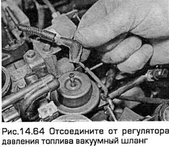
64. Disconnect the vacuum hose from the fuel pressure regulator (see fig. 14.64).
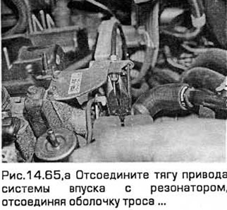
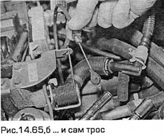
65. Disconnect the drive rod of the intake system with a resonator, disconnecting the cable and its sheath (see fig. 14.65, a, b).
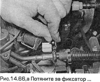
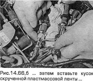
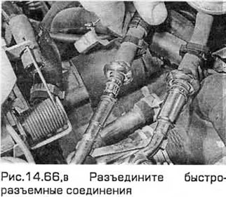
66. Disconnect the fuel supply and return fuel lines, releasing their quick couplings (see fig.14.66,a-c).
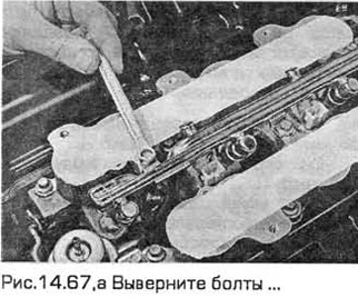
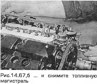
67. Remove the bolts and remove the fuel line from the lower section of the intake manifold (see fig.14.67,a-c). The injectors can be removed along with the line or left in the intake manifold.
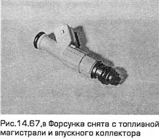
68. Remove the injectors from the bottom section of the intake manifold or line and place them in a clean container.
All models
69. Remove and discard all O-rings. The subsequent operations of checking the fuel injectors are beyond the power of the car owner. If you doubt the correctness of the injector (OK), contact your dealers.
Installation
70. Installation - in the reverse order of removal, taking into account the following:
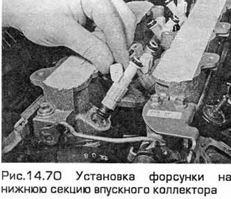
- A) Lubricate new O-rings with clean engine oil. Install the injectors on the lower section of the intake manifold, and then install the fuel line on them (see fig. 14.70).
- b) Tighten the line bolts to the required torque.
- V) Finally, turn the ignition on and off five times to start the fuel pump and restore pressure in the system (without cranking the engine). Before starting the engine, check for fuel leaks in the area of the connections that you disassembled.
Fuel pressure control
Withdrawal
71. Relieve residual pressure in the fuel system (paragraph 2) and equalize the pressure in the tank by removing the tank cap.
Warning: Be aware that fuel remains in system components when residual pressure is released and take precautions before disconnecting them.
72. Disconnect the negative battery cable (chapter 5 paragraph 1).
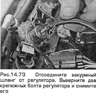
73. On models with 4-cylinder engines manufactured before 07.1997, remove the intake air duct chamber (paragraph 4) and disconnect the vacuum hose from the regulator. Unscrew the two fixing bolts of the regulator and, having overlaid it with rags to absorb the escaping fuel, remove the regulator (see fig.14.73). On models with 4-cylinder engines manufactured from 07.1997, you must also disconnect the fuel outlet hose and release it from the retainer. Remove the O-ring. Remove fuel spills with a clean rag.
74. On models with V-shaped 6-cylinder engines of release before 07.1997, remove the highway, as indicated above. On late models, remove the upper section of the intake manifold. Disconnect the vacuum hose from the regulator. Turn out two fixing bolts of a regulator and, having overlaid it with rags for absorption of the following fuel, remove a regulator. Remove the O-ring. Remove fuel spills with a clean rag.
Installation
75. Installation - in the reverse order of removal, taking into account the following:
- A) Always replace the O-ring when removing the regulator. Lubricate the new ring with clean engine oil.
- b) Establish a regulator in a dredging of a fuel highway and tighten bolts the demanded moment.
- V) Finally, turn the ignition on and off five times to start the fuel pump and restore pressure in the system (without cranking the engine). Before starting the engine, check for fuel leaks in the area of the connections that you disassembled.
Idle speed control valve
Withdrawal
76. Disconnect the negative battery cable (chapter 5 paragraph 1).
77. On models with 4-cylinder engines, lift the front end and place it on supports (see fig. 14.77).
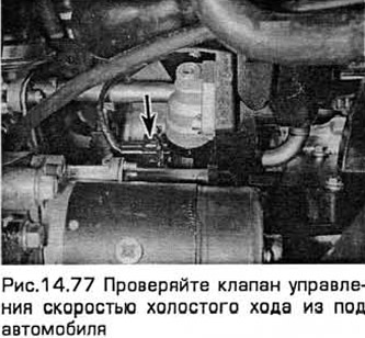
Warning: Do not work under the vehicle if it is only supported by a jack!
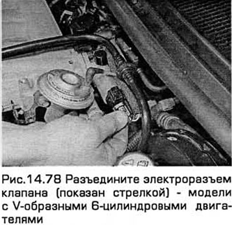
78. Disconnect the valve connector (see fig.14.78).
79. Turn out two fixing bolts (on models with 4 cylinder engines) or nuts (on models with V-shaped 6-cylinder engines) and remove the valve from the intake manifold (see fig. 14.79). Remove the gasket.
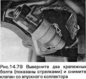
80. Since the valve components are not supplied separately and the entire assembly must be replaced in the event of a malfunction, you can try flushing the channels with carburetor flushing agent or something similar. It won't take long and. may lead to troubleshooting.
Installation
81. Installation - in the reverse order of removal, taking into account the following:
- A) Rinse mating surfaces thoroughly. Always install a new gasket after valve removal.
- b) Tighten the bolts evenly to the correct torque.
- V) Immediately after connecting the wiring and battery, start the engine and idle it. After it has warmed up to normal operating temperature, check that the idle speed has not changed and that there are no air leaks. Turn on all electrical consumers (headlights, rear window defroster) and check that the idle speed remains within the specified value.
Idle speed increase valve
Withdrawal
82. If necessary, to improve access, you can remove the intake air duct chamber (paragraph 4).
83. Disconnect the negative battery cable (paragraph 1 chapter 5).
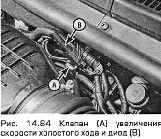
84. Disconnect the valve electrical connector. Unclip the valve from the baffle and then disconnect the vacuum hoses and remove the valve (see fig. 14.84).
Installation
85. Installation - in the reverse order of removal.
Visitor comments