Contents: Air Cleaner Assembly - 4 Cylinder… ↳ Air Cleaner Assembly - V6 Engines ↳ Intake Duct Resonator - Early Model… ↳ Air Intake Chamber - Early Model 4… ↳ Components located under the wing ↳
Air Cleaner Assembly - 4 Cylinder Engines
Removal
1. Disconnect the negative battery cable (Chapter 5, paragraph 1).
2. Remove the air flow meter from the air cleaner cover (Chapter 6).
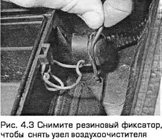
3. Remove the rubber retainer from the air cleaner on its left side (see Fig. 4.3).
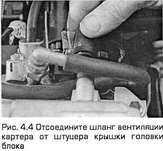
4. Disconnect the crankcase ventilation hose from the air cleaner housing or from the cylinder head cover fitting (see Fig. 4.4).
5. Remove the air cleaner assembly by lifting it off the bushings and separating it from the intake duct in the inner fender panel.
Installation
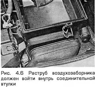
6. Installation - in the reverse order of removal. Make sure that the housing projections are seated in the bushings and the air cleaner bell is fully inserted into the connecting bushing (see Fig. 4.6).
Air Cleaner Assembly - V6 Engines
Removal
7. Disconnect the negative battery cable (Chapter 5, paragraph 1).
8. Disconnect the wiring from the intake air temperature sensor on the side of the air cleaner.
10. Loosen the clamp and disconnect the hose from the air cleaner outlet.
11. On early models, remove the rubber retainer from the air cleaner on the left side.
Note: Later models do not have this lock.
12. Remove the air cleaner assembly by lifting it off the bushings and disconnecting the air intake duct on its left side.
13. Inspect the mounting bushings and replace them if necessary.
Installation
14. Install the bushings onto the bracket correctly.
15. Place the housing protrusions into the bushings and attach the air intake duct.
16. Place the rubber retainer (if equipped) onto the air cleaner on its left side.
17. Connect the hose to the air cleaner outlet and tighten the clamp.
Note: Pay attention to the position of the mounting lug.
18. Connect the wiring to the air temperature sensor.
19. Connect the wiring to the air flow meter.
20. Connect the negative battery cable (Chapter 5, paragraph 1).
Intake Duct Resonator - Early Model 4 Cylinder Engines
Removal
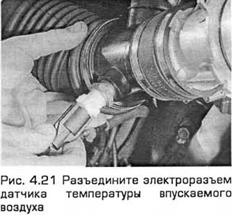
21. Remove the resonator support bracket bolts from the front crossmember of the engine compartment. Loosen the screws of the two clamps securing the resonator to the air flow meter hoses and the intake air duct chamber. By tilting the resonator away from the thermostat housing, disconnect the electrical connector of the intake air temperature sensor (see Fig. 4.21). Remove the resonator.
Installation
22. Installation - in the reverse order of removal.
Air Intake Chamber - Early Model 4 Cylinder Engines
Removal
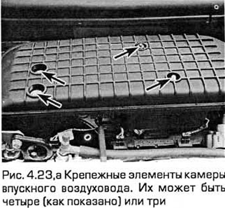
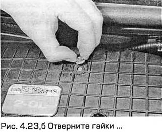
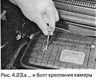
23. Pull out the rubber plugs covering the chamber fasteners and remove the fasteners (see Fig. 4.23,a-c). Loosen the screw securing the intake air duct chamber to the hose or resonator. Alternatively, the air flow meter can be detached from the air cleaner.
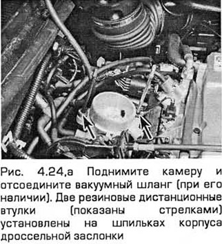
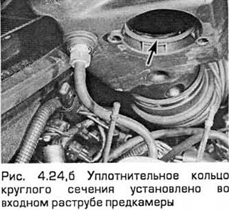
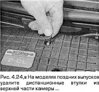
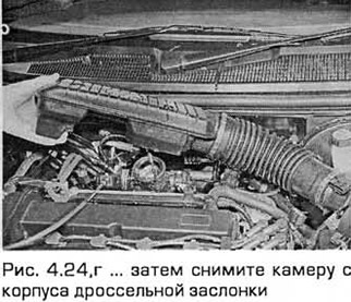
24. Lift the chamber and disconnect the vacuum hose (if any) from its lower side. Pull out the pre-chamber, pay attention to the two rubber spacer bushings (installed on the studs of the throttle body), as well as the O-ring installed in the inlet bell of the pre-chamber (see Fig. 4.24, a-g).
Installation
25. Installation - in the reverse order of removal. Securely install the O-ring and bushings.
Components located under the wing
Removal
26. Remove the left wheel arch liner (Chapter 11).
27. Unscrew the bolts and remove the air intake and both resonators.
Installation
28. Installation - in the reverse order of removal.