Contents: Removal ↳ Installation ↳
Warning: Before you begin, read the warning in paragraph 1 this chapter.
Removal
Note: This operation requires Tool 23-038, a large socket wrench with protruding teeth that fit into the slots of the fuel pump/gauge sensor retaining nut. You will also need an assistant.
1. Remove residual pressure in the fuel system (paragraph 2) and equalize the pressure in the fuel tank by removing the fuel tank cap.
Warning: Remember that after releasing residual pressure, fuel remains in the system components and take precautions before disconnecting them.
2. Make sure the ignition is off.
3. Remove the bolts or fold forward (depending on the version) the rear seat cushion (Chapter 11). Remove the plug from the floor of the vehicle covering the fuel pump/gauge sensor. Wash away any dirt from the outside of the tank and wipe it dry. Use a vacuum cleaner to clean the area inside the vehicle closest to the tank to prevent dirt, water or dust from getting into the tank when opening it.
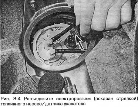
4. Disconnect the fuel pump/gauge sensor electrical connector (see Fig. 8.4).
5. To disconnect the fuel injection and drain pipes from the unit being serviced, release the coupling on each pipe by squeezing its locking tabs located on the fitting and pulling the coupling together. Remove any fuel leaks with a rag. If the coupling is difficult to remove, use pliers and a wooden shim to push the pipe out of the fitting. This may require considerable force. Be careful not to damage the components (see Fig. 8.5).

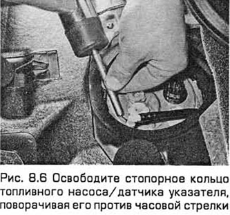
6. Loosen the fuel pump/gauge sensor retaining ring by turning it counterclockwise. Use the Ford approved tool 23-038. If you don't have one, you can use a hammer and punch or pliers. This will at least help with removal (see Fig. 8.6).
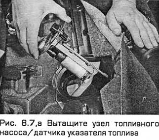
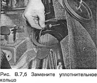
7. Pull out the unit so as not to bend the float lever. The float lever is mounted on a spring-loaded rod, which ensures that it is pressed against the bottom of the tank. Pay attention to the sealing ring. After removing the unit, it must always be replaced (see Fig. 8.7, a, b).
Installation
8. When installing, use a new O-ring and make sure the mesh filter located above the base of the pump inlet is clean.
9. Align the assembly with the opening in the tank and insert it so as not to bend the float. Make sure that the float lever slides along the rod until the upper support plate of the block can be aligned with the opening in the tank and pressed against the sealing ring. This will require some force. Do not damage the components. The specified Ford device ensures that the ring is pressed when screwed in without distorting it relative to the tank.
10. Press the assembly down while an assistant inserts and engages the retaining ring. Once it engages the tabs in the tank, turn the ring clockwise to tighten.
11. Perform the remaining installation operations in the reverse order of removal. Follow the color markings to install the fuel lines in their places.