Contents: Fuel system ↳ Air intake system ↳ Electronic control system ↳ Electronic control unit (ECU) ↳ Mass air flow meter ↳ Crankshaft Position/Speed Sensor ↳ Coolant temperature sensor ↳ Intake Air Temperature Sensor ↳ Throttle potentiometer ↳ Speedometer sensor ↳ Power steering pressure sensor ↳ Air conditioning system ↳ Idle Speed Control Valve ↳ Automatic transmission sensors ↳ Oxygen sensor ↳ Windshield Defogger Solenoid ↳
1. The vehicle is equipped with a sequential fuel injection system with electronic control. The system consists of three main subsystems: the fuel system, the air intake system and the electronic control system.
Fuel system
2. An electric fuel pump located inside the fuel tank forces fuel into the fuel line, from where it flows to the fuel injectors. A fuel filter is installed between the fuel pump and the fuel line. A pressure regulator controls the pressure in the system depending on the vacuum in the intake tract. From the fuel line, fuel is injected through four fuel injectors into the intake ports located directly above the intake valves. The system also includes a device for supplying cold fuel by means of a jet surrounding each fuel injector, which is used to improve the starting of a warm engine.
3. Fuel dosing by fuel injectors is carried out under the control of the electronic control unit BZU. This device receives signals from the crankshaft position/engine speed sensor and the camshaft position sensor and, depending on this, switches on the fuel injectors individually in accordance with the order of cylinder operation (sequential injection) to achieve low fuel consumption and the level of harmful substances emitted.
Air intake system
4. The air intake system contains an air filter housing, an air flow meter, an air intake duct, and a throttle body. The air flow meter, which uses a filament as a sensing element, sends a signal of changing voltage to the ECU in accordance with the volume of air entering the engine. Another sensor installed in the air flow meter monitors its temperature. Based on these signals, the ECU calculates the mass of air entering the engine.
5. The throttle valve, installed inside the housing, is controlled by the gas pedal. When it opens, the amount of air entering the system increases. The more the throttle valve potentiometer slider moves, the higher the signal level of the air flow meter. Accordingly, the ECU opens each injector for a longer time, due to which the amount of fuel entering the intake ports increases.
Electronic control system
6. The electronic engine management system (EEC-IV and EEC-V) controls the fuel injection system as well as other engine subsystems. It receives signal(s) from sensors that monitor various parameters such as intake air mass and temperature, coolant temperature, engine position and speed, acceleration/deceleration, and oxygen content in the exhaust gases. Based on these signals, the system determines the injection interval required to achieve the optimum air/fuel ratio. These sensors and relays controlled by the system are located in various places in the engine compartment.
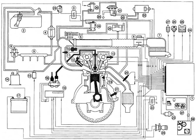 Fig. 12.6,a Engine management system - shows the fuel injection, ignition and emission control subsystems
1. ECU (electronic control unit)
2. Fuel pump/fuel gauge sensor
3. Fuel pump relay
4. Fuel filter
5. Idle speed control valve
6. Air flow meter
7. Air cleaner unit
8. Fuel pressure regulator
9. Fuel line
10. Throttle potentiometer
11. Intake air temperature sensor
12. Fuel injector
13. Camshaft position sensor
14. Carbon adsorber
15. Carbon adsorber purge valve
16. Ignition coil
17. Battery
18. Ignition module - removed from the ECU (only for models with automatic transmission)
19. Coolant temperature sensor
20. Oxygen sensor
27. Crankshaft position/speed sensor
22. Supply voltage relay
23. Steering hydraulic pressure sensor
24. Air conditioning compressor clutch solenoid
25. Octane switch electrical connector
26. Self-diagnostic connector for Ford STAR diagnostic tester
27. Self-diagnosis connector for FDS 2000 diagnostic tester
28. Ignition switch
29. Fuel cut-off switch
30. Exhaust gas recirculation solenoid valve
31. Exhaust gas recirculation valve
32. Exhaust gas recirculation system differential pressure sensor
33. Location for measuring the pressure difference of the exhaust gas recirculation system
34. To the intake manifold
35. Fuel afterburning system filter housing
36. Solenoid valve of the fuel afterburning system
37. Air conditioning/electric fan control unit
38. Automatic transmission control system (if equipped)
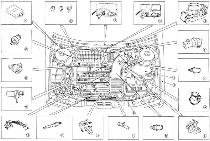 Fig. 12.6,b Location of the main components of the fuel injection, ignition and emission control subsystems on models with 4-cylinder engines
1. ECU (electronic control unit)
2. Self-diagnosis, diagnostics and maintenance connectors (from left to right)
3. Support bracket for components located on the bulkhead of the engine compartment (manual transmission, shown from left to right) - EGR solenoid valve, fuel afterburner solenoid valve, EGR differential pressure sensor
4. Support bracket for components located on the engine compartment bulkhead (automatic transmission, shown from left to right) - EGR solenoid valve, afterburner solenoid valve, EGR differential pressure sensor, and the ignition module located at the top
5. Throttle body with potentiometer
6. Idle speed control valve
7. Intake air temperature sensor
8. Air flow meter
9. Exhaust gas recirculation valve
10. Coolant temperature sensor
11. Crankshaft position/speed sensor
12. Fuel afterburning system filter housing
13. Oxygen sensor
14. High-voltage wires of the coil and spark plugs
15. Camshaft Position Sensor 1B Fuel Injector(s)
17. Steering hydraulic pressure sensor
18. Air cleaner unit
19. Air intake duct and resonators - under the front left fender
20. Resonator
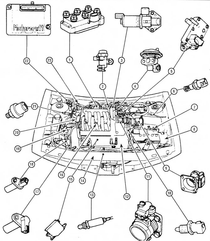 Fig. 12.6,c Location of the main components of the fuel injection, ignition and emission control subsystems on models with V-shaped 6-cylinder engines
1. Ignition coil
2. Electronic vacuum regulator
3. Idle air control valve
4. EGR system valve
5. Electronic differential pressure sensor
6. Intake air temperature sensor
7. Air purifier
9. Mass air flow meter
10. Coolant temperature sensor
11. Throttle position sensor and housing
12. Coolant pump drive belt cover
13. Heated oxygen sensor
14. Front catalytic converter (rear is mounted on the exhaust manifold of the rear cylinder head)
15. Air intake control unit through the intake manifold
16. Upper section of the intake manifold
17. Camshaft position sensor
18. Crankshaft position sensor
19. Engine hydraulic support
20. Right engine mount
21. Steering hydraulic pressure sensor
22. Power control module or electronic control device
23. Octane switch
7. In the event of a failure of any sensor, a backup circuit is activated, which provides control until the failure is eliminated.
Electronic control unit (ECU)
8. This is the main component of the engine management system, which controls the fuel injection, ignition and emission control subsystems. The ECU also controls the electric radiator fan, air conditioning system and automatic transmission (depending on the version).
Mass air flow meter
9. It is based on a filament that outputs a continuously changing (analog) voltage signal to the ECU in accordance with the mass of air entering the engine.
Crankshaft Position/Speed Sensor
10. This is an induction pulse generator mounted on the cylinder block (4-cylinder engines) or on the valve timing cover (V6 engines). It is designed to scan the projections located between 36 holes on the flywheel/faceplate (4-cylinder engines) or on a disc mounted on the crankshaft (V6 engines). When the projection is against the tip of the sensor, the latter generates a signal, based on which the ECU determines the engine speed.
11. There is no protrusion between the 35th and 36th holes (90° before TDC), and the pause when receiving the signal is perceived by the ECU as a reference mark corresponding to the position of the crankshaft.
Camshaft Position Sensor
12. On 4-cylinder engines, it is located on the rear left side of the cylinder head and secured with bolts. The sensor senses a protrusion located on the intake camshaft. On V-6 engines, the sensor is located on the front right side of the cylinder head. The sensor senses a protrusion located on the intake camshaft of the front cylinder head. It functions in the same way as the crankshaft position/speed sensor. As a result, the ECM has a reference point (46° after TDC for cylinder #1) to determine the firing order of the cylinders and to activate the fuel injectors in the appropriate sequence.
Coolant temperature sensor
13. The sensor is installed on the thread in the upper part of the thermostat housing (4-cylinder engines) or on the connecting pipe of the cooling system (V-shaped 6-cylinder engines). This is a thermistor, i.e. a semiconductor device whose resistance decreases as its temperature increases. It gives the ECU a continuously changing (analog) voltage signal in accordance with the temperature of the coolant. The ECU uses the information received to refine calculations in order to ensure the ideal ratio of the air-fuel mixture components.
Intake Air Temperature Sensor
14. On 4-cylinder engines, the sensor is mounted on a thread on the underside of the intake air duct resonator (models produced before 1997) or in the intake air duct (models produced since 1998). On V-shaped 6-cylinder engines, the sensor is mounted in the air cleaner cover. The sensor is based on a thermistor, the signal from which changes depending on the temperature of the air entering the engine. It is also used to refine the calculations performed by the ECU when determining the dose of injected fuel in order to achieve the ideal ratio of the air-fuel mixture components.
Throttle potentiometer
15. The component is installed on the end of the throttle shaft. Depending on the opening of the throttle valve, it sends an analog voltage signal to the ECU. Due to this, the ECU registers the driver's influence with the circuit for determining the dose of fuel injected into the engine.
Speedometer sensor
16. The sensor is installed on the speedometer drive. It is a pulse generator based on the Hall effect. The sensor sends a sequence of pulses to the ECU depending on the vehicle speed. Based on this information, the ECU controls such functions as fuel cut-off after the engine is turned off. Information from this sensor also goes to the on-board computer, the active suspension system, and the constant speed control device (depending on the version).
Power steering pressure sensor
17. The sensor is installed on the thread on the pressure pipeline of the hydraulic steering system. It has normally closed contacts that open when the system reaches the regulated pressure. Receiving this signal, the ECU increases the idle speed to compensate for the additional load on the engine.
Air conditioning system
18. To provide information about the operation of this system, two pressure sensors and a compressor clutch solenoid are connected to the ECU. The ECU can increase the idle speed or, if necessary, turn off the air conditioning system so that the vehicle's dynamic qualities are not impaired. See Chapter 3. Note that diagnostics and repair of this system are the competence of dealers.
Idle Speed Control Valve
19. The valve maintains a constant idle speed by changing the amount of air entering the engine through the auxiliary air channel. The valve is activated by a signal from the ECU.
Automatic transmission sensors
20. In addition to the components that transmit the driver's input to the transmission, it also has a speed sensor, a working fluid temperature sensor (built into the electromagnetic valve), and a selector position sensor. All of these sensors are connected to the ECU, which controls the transmission via the electromagnetic valve. See Chapter 7B.
Oxygen sensor
21. The sensor installed in the exhaust system provides the ECU with a continuous feedback signal. This allows the mixture composition to be adjusted to ensure optimum operation of the catalytic converter. See Chapter 4B.
Windshield Defogger Solenoid
22. When the windshield heater is turned on, the solenoid allows extra air into the intake manifold to compensate for the extra load on the generator.