Contents: Models with 4-cylinder engines… ↳ Models with 4-cylinder engines and… ↳ Models with V6 engines and traction… ↳
Models with 4-cylinder engines without traction control
Removal
1. Disconnect the negative battery cable (Chapter 5, paragraph 1).
2. Remove the camera (section 4).
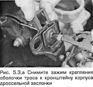
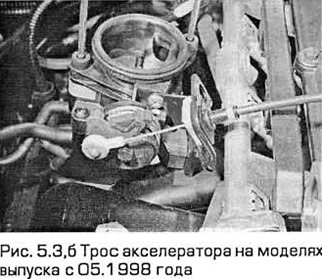
3. Remove the clamp securing the cable sheath to the throttle body bracket (see Fig. 5.3,a,b). Disconnect the cable end from the throttle lever mechanism and release the cable from all clamps and connections.
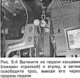
4. Inside the passenger compartment - in the area located above the gas pedal, pull the end switch and bushing out of the pedal, and then release the cable, pulling it out through the slot in the pedal (see Fig. 5.4). Tie a rope to the end of the cable.
5. Pull the rope into the engine compartment through the bulkhead until you can untie the rope and remove the rope.
Installation
6. Installation - in the reverse order of removal. Pull the cable through the partition using the rope.
7. Adjust the cable as shown below.
Adjustment
8. Remove the intake air plenum (paragraph 4).
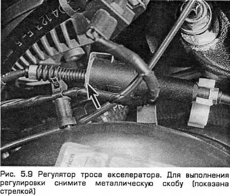
9. Locate the cable adjuster. It is located on the throttle body bracket or about two-thirds of the way from the end of the cable and is secured to the right front suspension strut support (see Fig. 5.9). Remove the metal clamp and lubricate the adjuster bushing with soapy water.
10. Take up the slack by pulling the cable out of the regulator. Have an assistant fully depress the gas pedal. This will cause the cable sheath to slide back into the regulator. Hold it in this position and install it in the clamp.
11. Make sure the throttle moves smoothly throughout its travel (from fully open to fully closed and back) as your assistant presses and releases the accelerator pedal. Readjust the cable if necessary.
12. After completing the adjustment, install the camera (paragraph 4).
Models with 4-cylinder engines and traction control system
Note: The procedure in this subparagraph applies to the entire cable. Note that the sections of cable that connect the pedal to the actuator and the actuator to the throttle body are supplied separately. They can be removed and installed separately, and if you do so, follow the procedure in this subparagraph mutatis mutandis.
Removal
13. Disconnect the negative battery cable (Chapter 5, paragraph 1).
14. Remove the camera (section 4).
15. Remove the clamp securing the cable housing to the throttle body bracket. Disconnect the cable end from the throttle linkage and release the cable housing from all clamps and connections.
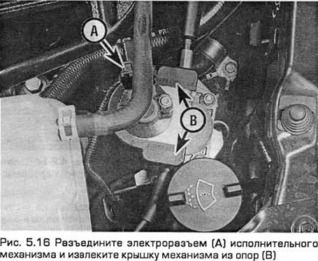
16. Disconnect the electrical connector of the traction control system actuator and remove the mechanism cover (see Fig. 5.16).
17. Considering how the cable sections are connected to the pulleys, disconnect the end of the first cable from the upper pulley of the throttle actuator. Then pull the cable housing up out of the actuator housing. Disconnect the second cable from the lower pulley of the actuator in the same manner.
18. Inside the passenger compartment - in the area located above the gas pedal, pull the end switch and bushing out of the pedal, and then release the cable, pulling it out through the slot in the pedal. Tie a rope to the end of the cable.
19. Pull the rope into the engine compartment through the bulkhead until you can untie the rope and remove the rope.
Installation
20. Installation - in the reverse order of removal. Using a rope, pull the cable connecting the pedal to the actuator through the partition. Make sure that the ends of the cables are connected to the corresponding pulleys of the actuator.
21. Adjust both cables as follows.
Adjustment
Note: Both cable sections must be adjusted together, even if you only removed one of them.
22. Remove the camera (section 4).
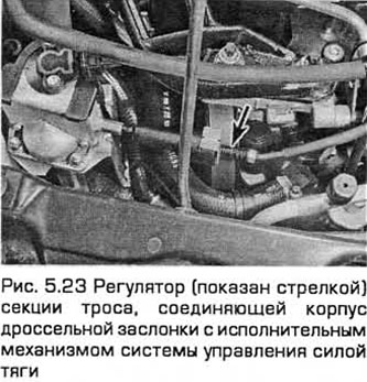
23. Remove the metal clip from the adjuster of each cable section (see Fig. 5.23). Lubricate the adjuster bushings with soapy water.
24. Take up the slack by pulling both cable sheaths as far as possible out of their respective adjusters.
25. Disconnect the traction control actuator electrical connector and remove the actuator cover. Lock both pulleys together by inserting a suitable sized rod into their alignment holes. Disconnect the actuator-to-throttle body cable end from the throttle linkage.
26. Ask your assistant to fully depress the gas pedal. This will cause the cable sheath connecting the pedal to the actuator to re-enter the regulator. Hold it in this position and install the clamp.
27. Attach the end of the cable connecting the actuator to the throttle body to the throttle linkage. Make sure that the cable housing bushing is properly secured in the housing bracket.
28. Again, have your assistant fully depress the accelerator pedal. The cable housing that connects the actuator to the throttle body should re-enter the regulator. While holding it in this position, install the clamp.
29. Remove the locking pin from the pulleys. Check that the throttle valve moves smoothly through its entire travel (from fully open to fully closed and back) as your assistant presses and releases the gas pedal. Readjust the cable(s) if necessary.
30. After completing the adjustment, install the traction control actuator cover and electrical connector, as well as the pre-chamber (paragraph 4).
Models with V6 engines and traction control system
Note: The procedure in this subparagraph applies to the entire cable. Note that the sections of cable that connect the pedal to the actuator and the actuator to the throttle body are supplied separately. They can be removed and installed separately, and if you do so, follow the procedure in this subparagraph mutatis mutandis.
Removal
31. The accelerator cable consists of a primary and a secondary section. The primary section is connected to the accelerator pedal and the traction control actuator located in the right front corner of the engine compartment. The secondary section is connected to the traction control actuator and the sector on the throttle body.
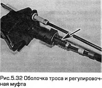
32. Pull the clamp and remove the secondary section casing from the bracket (see Fig. 5.32).
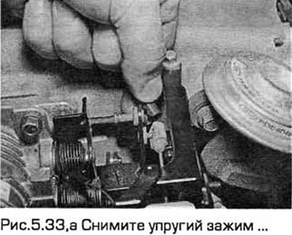
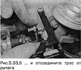
33. Disconnect the cable from the sector or lever on the throttle body. Where necessary, remove the elastic clamp (see Fig. 5.33, a, b).
34. On models produced from 01/1997, disconnect the secondary cable section housing from the clip on the left wing inner panel.
35. Unhook the secondary cable section sheath from the clamp at the front of the cable section.
36. Disconnect the wiring from the traction control motor.
37. Carefully remove the cover from this engine (Chapter 9, paragraph 24).
38. Disconnect the secondary section of the cable from the upper quadrant on the engine. Then disconnect the secondary section cable housing from the bracket on the engine.
39. Release the sheath from the fasteners and disconnect the primary section of the cable from the lower sector on the engine. Disconnect the primary section sheath from the bracket on the engine.
40. Inside the passenger compartment, disconnect the primary cable section from the gas pedal. Tie a rope to the end of the cable section sheath.
41. Pull the cable into the engine compartment through the bulkhead until the rope can be untied and the primary section of the cable removed.
Installation and adjustment
42. Installation - in the reverse order of removal. Using a rope, pull the cable connecting the pedal to the actuator through the partition. Make sure that the ends of the cables are connected to the corresponding sectors of the actuator.
43. Adjust both cables (paragraph 23...30).