Contents: Intake Duct/Throttle Body Assembly ↳ Additional air valve assembly ↳ Throttle Position Sensor (TP) ↳ Fuel rail ↳ Fuel injectors ↳ Fuel pressure regulator ↳
Replacement of electronic fuel injection (EFI) components for 1991 four-cylinder engines and all 3.0LV6 engines.
Note: Replacing most components requires complete disassembly of the entire EFI system. To determine what specifically needs to be disassembled, carefully read the section and those paragraphs that pertain to the parts to be replaced.
Intake Duct/Throttle Body Assembly
Note 1: If you are replacing the intake manifold/throttle body gasket, you do not have to remove the various parts attached to the throttle body. Remove the entire assembly as recommended below.
Note 2: Information specific to 1991 four-cylinder engines is provided in paragraphs 15 through 24 in Section 14.
Disassembly
1. Unscrew the fuel filler cap.
2. Relieve the pressure in the fuel system (see section 2).
3. Disconnect the negative battery cable.
4. Loosen the hose clamps and disconnect the air cleaner connecting tube, which is located between the air cleaner and air throttle housings.
5. Disconnect the electrical connector from the throttle position (TP) sensor, secondary air valve, air temperature (ACT) sensor and exhaust gas regulation (EGR) electronic converter.
6. Disconnect the throttle cable from the throttle connection (see section 9).
7. Mark and then disconnect the main branch vacuum line, pressure regulator, and MAP sensor vacuum line from the vacuum line branch. Disconnect the vacuum line from the EGR valve.
8. Disconnect the PCV hose from the PCV valve (see chapter 1). On four-cylinder engines, remove the pressure and return lines.
9. Unscrew and disconnect the EGR pipe from the EGR valve (see Chapter 6). On a four-cylinder engine, remove the upper intake manifold support brackets.
10. On V6 models, remove the generator support bracket nut from the stud at the far right end of the intake manifold (passenger side), loosen the nut at the other end of the bracket, and remove the support bracket (see Chapter 5).
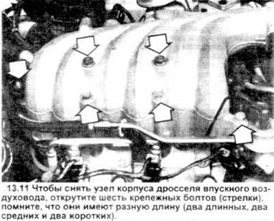
11. Remove all the intake air duct bolts, including the stud mentioned in the previous paragraph (see picture). Remember that on V6 type models, bolts of different lengths are used (two long, two medium and two short). The bolts should be screwed into the holes from which they were unscrewed.
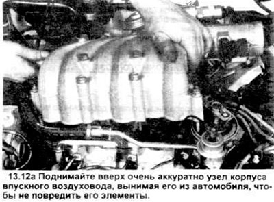
12. Remove the intake air duct/throttle body assembly (see illustrations).
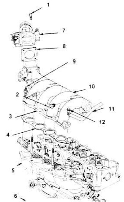
13.12, b. 3D rendering of upper intake manifold and throttle body (1991 four-cylinder engine).
1. Bolt M6x1x30 (4 pieces).
2. Nipple.
3. Lid.
4. Gasket.
5. Lower intake manifold assembly.
6. Front of the engine.
7. Throttle body assembly.
8. Gasket.
9. Bolt - stud M8x1.25x35x12.
10. Upper intake manifold assembly.
11. PCV hose.
12. Bolt M8x1.25x35 (4 pieces).
12. Remove the intake air duct/throttle body assembly (see illustrations).
13. Remove and discard the old gasket.
13. Remove and discard the old gasket.
Installation
14. Clean and inspect the mating surfaces of the throttle body and lower intake manifold. Both surfaces should be clean and flat.
15. Clean and lubricate the manifold stud threads.
16. Install a new gasket.
17. Using the guide pins as guides, secure the throttle body assembly to the lower intake manifold.
18. Screw six bolts (two long, two medium, two short) each into its own hole and tighten them to the required tightening torque.
19. Assembly is carried out in the reverse order of disassembly.
Additional air valve assembly
Disassembly
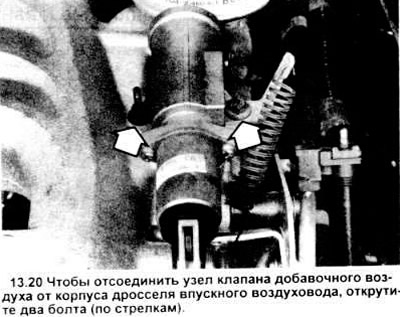
20. Pull out the electrical connector of the additional air valve (see figure).
21. Loosen the snow guard bolts and remove the snow guard (if equipped).
22. Unscrew the two retaining screws.
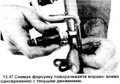
23. Remove the additional air valve and gasket. Discard the old gasket.
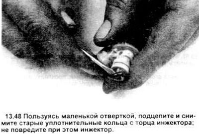
Installation
24. Ensure that the mating surfaces of both the throttle body and valve gasket are clean.
25. Install the gasket on the throttle body surface and put the additional air valve in place. Tighten the mounting screws.
26. Installation is carried out in the reverse order of disassembly.
Throttle Position Sensor (TP)
Removal
27. Pull out the throttle position sensor electrical connector (see figure).
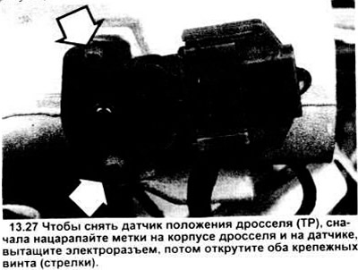
28. Scratch marks on the throttle body and throttle position sensor to accurately align their relative positions during installation.
Note: The TP sensor is not adjustable, so these marks are very important.
29. Remove the two throttle position sensor retaining screws.
30. Remove the throttle position sensor.
Installation
31. Make sure the sensor pivot tabs are oriented correctly and the red gasket is inside the connector housing. Position the pivot tabs over the throttle shaft blade, then rotate the throttle position sensor (TPS) clockwise until it seats.
Caution: Installing the sensor in any other way may result in increased idle speed.
32. Align the marks on the throttle body and the sensor on the throttle body with the two locking screws.
33. Installation is carried out in the reverse order of disassembly.
Fuel rail
Removal
34. Remove the intake air duct throttle body (see above).
35. Disconnect the vacuum lines from the fuel pressure regulator.
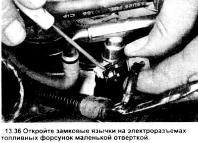
36. Using a small screwdriver, carefully remove the fuel injector electrical connectors (see illustration).
37. Using a special Ford spring-lock tool (3/8 inch for the front connector and 1/2 inch for the rear) or equivalent, disconnect the fuel line ends, as well as the fuel supply and return lines (see section 3).
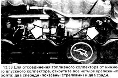
38. Unscrew the fuel injector manifold mounting bolts (see figure).
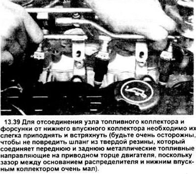
39. While lifting and gently shaking the fuel rail, carefully separate the rail assembly and the fuel injectors.
40. For instructions on replacing injectors, O-rings or fuel pressure regulator, see below.
Installation
41. Lubricate all lower O-rings with clean engine oil.
42. Carefully install the fuel rail and injector assembly into the lower intake manifold, one side at a time. Press down on the rail to ensure the O-rings are seated.
43. While holding the guide assembly in place, hand tighten the bolts, one at a time on each side, then tighten them down.
44. Installation is carried out in the reverse order of disassembly.
Fuel injectors
Disassembly
45. Remove the intake air duct throttle body (see above).
46. Remove the fuel rail assembly (see above).
47. Remove each of the injectors, while pulling the injector and simultaneously rotating it from side to side (see figure).
48. Carefully lift with a small screwdriver and remove the sealing rings (see figure).
Caution: Handle the injector and fuel manifold with extreme care to prevent damage to the sealing surfaces and fuel spray holes, which are very sensitive.
49. Make sure the injector caps are clean, undamaged and not contaminated.
Installation
50. The nozzles are installed using rotary and pushing movements.
51. Installation is carried out in the reverse order of disassembly.
Fuel pressure regulator
Removal
Note: If you have a special tool, it is not necessary to remove the fuel rail assembly to remove the pressure regulator. Otherwise, this assembly must be removed.
52. Remove the fuel filler cap.
53. Relieve the pressure in the fuel system (see section 2). On 4-cylinder models, remove 3 screws and fuel rail screen.
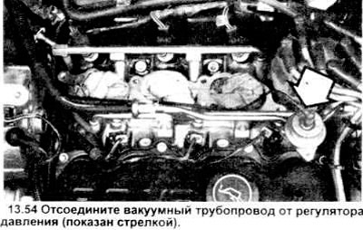
54. Disconnect the vacuum line from the pressure regulator (see figure).
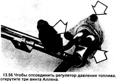
55. If you have a right-hand tool, remove the three Allen screws from the bottom of the pressure regulator base plate.
56. If you do not have the necessary tool, first remove the fuel rail assembly (see above), and then unscrew the screws (see figure).
57. Remove the pressure regulator assembly, gasket and sealing ring. Replace the ring and gasket.
Installation
58. Make sure that the sealing surfaces of the pressure regulator and fuel rail are clean. When using a scraper, be careful not to damage the working surfaces of the regulator and the gaskets of the supply line.
59. Lubricate the pressure regulator O-ring with clean oil.
60. Install a new O-ring and gasket onto the regulator.
61. Install the fuel pressure regulator onto the fuel rail assembly and tighten the three mounting screws.