Warning: Depressurize the fuel system before disconnecting lines and hose ends (section 2). Gasoline is highly flammable, so special care must be taken when working with any part of the fuel system.
Threadless connectors - assembly and disassembly
1. There are two types of threadless pipe connectors used in Ford vehicles. 3/8" and 5/16" lines use a fork-type connection, and 1.4" lines use a harpoon latch connection.
The assembly procedure for these connections is different. The clips should be replaced each time you disassemble.
2. Separate all pipelines from system elements: fuel filter, carburetor or injector, gas tank, etc. before removing the assembly.
3/8" and 5/16" connectors (with insert fork)
3. Inspect the connection - there may be dirt on it. Clean the connection before disassembly.
4. For a long service life, the pipeline can "grow together" - rotate the tubes relative to each other and move them in the axial direction.
5. Bend the tab of the latch and, slightly spreading its legs, push them into the case. After that, pulling the triangular protrusion, pull the latch out of the case. Remember that this part of the job is done without any tools.
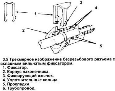
6. Pull tubing out of handpiece.
7. Do not reuse the retainer. Always replace with new.
8. Wipe the end of the tubing with a clean rag before installing the tip on the tubing. Check if there is dirt in it.
9. When connecting the handpiece to the pipeline, align them and push one into the other. Then install the retainer by inserting its legs into the holes in the body of the handpiece and pushing the triangular protrusion with your finger until the tabs lock it. The top of the triangular ledge must be directed away from the pipeline.
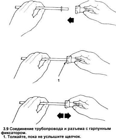
1/4" connectors (with harpoon latch)
10. Harpoon lock connector consists of body, intermediate rings, seal and retainer (see picture).
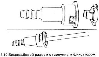
The retainer securely holds the tubing inside the handpiece. To disconnect the connector, use one of the two methods below.
11. Before starting work, check if dirt has accumulated in the inside of the handpiece that is visible to the eye. Tip should be cleaned before disassembly
12. For a certain time, the tip and pipeline "stick together". Turn the tip in the pipe, then move it along the axis until. until it moves freely.
13. The most preferred method of disconnection requires the use of a special tool. Align the groove of the special assembly-disassembly tool (parts of Ford NT82L -9500 - AH or similar) with corresponding latch lug (is at a 90 degree angle to the slots on the side of the latch), and insert the tool (see picture). This will separate the connector and tubing.
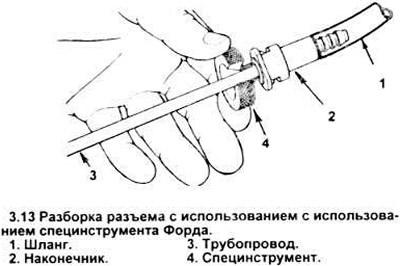
Note: Some fuel lines have a secondary lip that aligns with the outer surface of the connector. It may interfere with the insertion of the instrument. In this case, use the alternative disassembly method described in point 16.
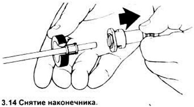
14. While holding the instrument and tubing with one hand, remove the handpiece (see picture).
Note: A moderate amount of force is sufficient if the clip is properly disengaged. It is recommended to use only hands.
15. After disassembly, check and clean the sealing surfaces of the pipeline. Inspect the inner surfaces of the pipe and tip - foreign parts from the connector may have entered there. Deformed parts should be replaced.
16. Alternative disassembly procedure requires Chanelok pliers. The width of the working part they should be no more than 3/16 inches.
17. Place the jaws of the pliers on the holes on the side of the tip and squeeze the latch that secures the body with them. The latch will separate from the body (it is necessary that both parts of the retainer are released at the same time).
18. Remove tubing from handpiece.
Note: If the clip has been released correctly, moderate force will be required. Do not use auxiliary tools.
19. After removing the connector from the pipeline, check if any parts have fallen into the inside of the pipe or tip. Lost parts should be replaced.
20. The retainer must remain on the pipeline. To remove, it must be freed from the pipeline shoulder. Do not install a used retainer - only a new one.
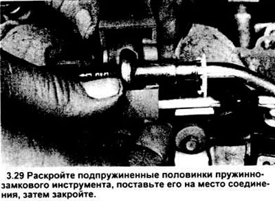
21. Before installing the connector, clean the piping with a clean rag. Check the inside surface of the connector - make sure there is no dirt or foreign objects.
22. When installing the tip, align it with the pipe and push it into place. At the time of installation, a characteristic click will be heard. Pull on the tip to make sure it is firmly in place.
23. Making one of the jagged ends "duck nose" into the hole. install a new clamp. At the same time, pull on the other side until the clip snaps into place.
Spring-lock pipeline connectors - assembly and disassembly
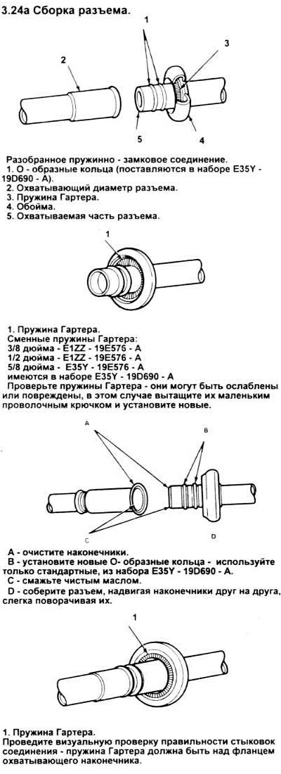
24. On used in a number of engines with CFI and EFI systems, fuel inlet and outlet pipelines use spring-lock connections instead of plastic ones "jogging" hose and pipe ends. The male end of the spring-and-lock connection, girded with two O-rings, is inserted into the female end of the flanged tube extending from the engine. The reliability of the connection is increased by the Harter spring, which prevents one tip from slipping out of the other (see picture).
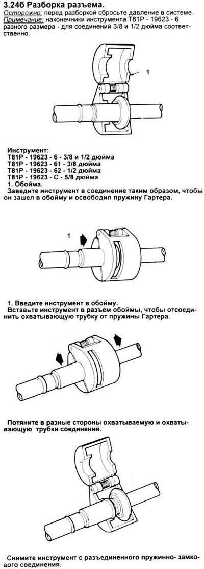
25. The diameters of the connectors of the inlet and outlet pipelines are different. A D87L - 9280 - B or similar spring lock tool will be required to disconnect a 1/2" inlet connector, a D87L - 9280 - A or equivalent will be required for a 3/8" outlet connector.
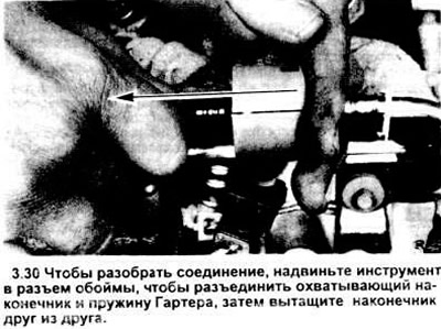
Connection separation
26. Relieve pressure in the system before disconnecting the tips included in the spring lock (see section 2).
27. Disconnect the negative battery cable.
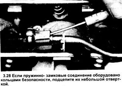
28. Using a small screwdriver on each tip, pry up the safety latch (see picture).
29. Replace the release tool, approximating the size of the (see picture).
30. Close the body of the tool, slide it into the open part of the holder to decompress the Harter spring and release the female tube (see picture).
Note: The spring may not expand if you hit the tool while sliding it into the cage slot.
31. When the spring is released, pull the tips out of each other.
32. Remove the tool.
Connection assembly
33. Make sure the Harter spring is in the male tip cage. If missing, insert a new one into the clip connector. If damaged, pull it out of the clip with a small hook (do not use a screwdriver) and install a new spring (Fig. 3.24 shows the standard sizes of springs).
34. Clean both mating parts of dirt and foreign objects.
Warning: use only standardized o-rings, they are made of special material, installation of non-standard rings can lead to leaks.
35. Lubricate the male lug, O-rings, and inside of the female lug with clean engine oil.
36. If the assembly includes a plastic indicator ring, install it in the cage slot.
37. Insert the female and male tips into each other and slide until the Harter spring compresses the female tube flange.
Note: if there is a plastic indicator ring, it will be pressed out from the cage connector, indicating by this the moment of assembly of the connection. In the absence of an indicator ring, visually check that the Harter spring has compressed the flange of the female lug (see picture).
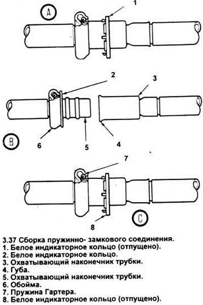
A) reinstall the white indicator ring before disassembling the joint; it may have slipped along the pipe.
b) after separating the tips, insert the white indicator ring into the ferrule of the female tip.
V) later, during assembly, the white indicator ring will freely pop on the cage of the male tip until the connection is fully assembled.
Visitor comments