Contents: Main elements of the EEC-V fuel… ↳ Actuators and devices of the EEC-V… ↳ Exhaust gas recirculation system for… ↳ Diagnostic elements in the EEC-V… ↳
Power supply system
Sequential fuel injection (SF1).
4 nozzles.
Air intake system
Air flow meter (MAF sensor) with heated wire element.
Electronic digital ignition system
Integrated electronic ignition system with electronic digital control (EDIS module is integrated into the EDIS control unit in the EEC-V-PCM).
Security system switch
The mechanical switch for the security system is mounted on the side in front of the driver's door.
Adjustment of exhaust gas composition
A catalytic converter (TWC) installed in the exhaust pipe.
Heated oxygen sensor (HO2S) installed in the exhaust manifold.
Exhaust gas recirculation (EGR) system.
Fuel vapor recovery system (EVAP).
Diagnostic capabilities
The central diagnostic connector (DLC) is located behind the left front pillar side trim.
Diagnostics of the processor (CPU) with the FDS 2000 device.
Main elements of the EEC-V fuel injection system
Control unit EEC-V-PCM.
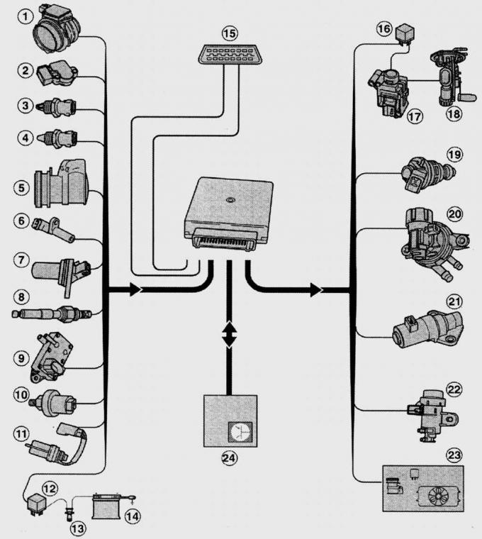
Fig. 8.2. Main elements of the EEC-V fuel injection system: 1 – air flow meter (MAP); 2 – Throttle position sensor (TP); 3 – Engine Air Temperature (IAT) sensor; 4 – Coolant temperature sensor (ECT); 5 – air conditioning compressor clutch; 6 – Crankshaft angle sensor (CKP); 7 – Camshaft Position Sensor (CMP); 8 – oxygen sensor (HO2S); 9 – electronic differential pressure transducer; 10 – Power steering switch (PSP); 11 – Speed sensor (VSS); 12 – relay; 13 – ignition switch with anti-theft device; 14 – battery; 15 – Diagnostic connector (DLC); 16 – Fuel pump relay (FPR); 17 – Battery Fuse Switch (IFS); 18 – Fuel pump (FP); 19 – nozzle; 20 – Evaporative emission control system electromagnetic valve EAVAP; 21 – Engine idling crankshaft speed control valve (IAC); 22 – vacuum regulator of the exhaust gas recirculation system EGR (EVR); 23 – Air conditioning fan switch; 24 – Engine Start Interlock (PATS)
The electronic control unit continuously monitors the engine operating conditions based on the information from the sensors (Fig. 8.2). The analog-to-digital converter converts the filtered input signals, such as crankshaft speed, absolute pressure in the intake manifold, coolant temperature, etc., into digital form, which allows all the information to be processed in the microprocessor before transmitting it to the output circuits. The output amplifier circuits convert low-power signals into signals of the power required by the various actuators of the system. Depending on the load and temperature, the control unit sends an output signal to inject a certain amount of fuel. In doing so, the control unit varies the opening time of the electromagnetic fuel injectors. The control unit memory stores programs and installation data. The EEC-V-PCM control unit allows reprogramming to newer engine control programs using the FDS 2000 device.
Fuel injection system battery safety switch.
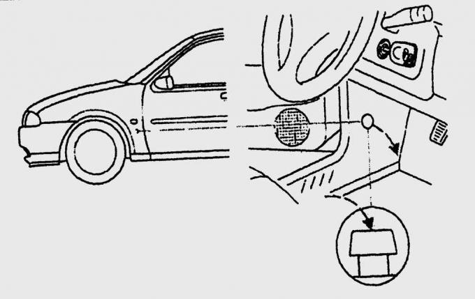
Fig. 8.3. Location of the fuel injection system battery safety switch
On all Fiestas (except diesel vehicles), the switch is located on the side in front of the driver's door (Fig. 8.3). The switch interrupts the fuel supply in the event of an accident or severe impact.
Air Flow Meter (MAF Sensor) -
installed before the throttle assembly, it measures the mass of air entering the engine. After passing the air filter, the air entering the engine passes through an air flow meter with a heated wire element, which forms part of an electric bridge circuit. The current passing through this wire element maintains its temperature at a constant level, which is higher than the temperature of the intake air.
At idle speed with the throttle valve closed, only a small amount of air passes by the heated wire element, which causes its slight cooling. When the accelerator pedal is pressed and the throttle valve is opened more, more air passes by the wire element and its degree of cooling increases.
Due to the decrease in temperature, the wire element changes its electrical resistance and the electric current flowing through it. This change in current informs the control unit about the amount of air entering the engine. In this way, changes in air pressure and temperature can be taken into account. The wire element air flow meter has no moving parts and its aerodynamic resistance inside the intake tract is insignificant.
The signals from the MAF sensor affect the adjustment and operation of the following systems:
- the amount of fuel injected into the engine cylinders;
- ignition timing angle;
- the position of the engine crankshaft speed control valve at idle (IAC);
- fuel Vapor Recovery (EVAP);
- exhaust gas recirculation (EGR);
- oxygen regulation.
Throttle Position (TP) Sensor -
is installed directly in the throttle assembly, is driven by the throttle shaft and records the current position of the throttle valve.
The sensor signals affect the adjustment and operation of the following systems:
- the amount of fuel injected into the engine cylinders;
- engine crankshaft speed at idle;
- ignition timing angle;
- exhaust gas recirculation (EGR).
Engine Air Intake Temperature Sensor -
is installed in the plastic housing of the air filter. The sensor signals are important for adjusting the following:
- the amount of fuel injected into the engine cylinders;
- engine crankshaft speed at idle.
Coolant Temperature (ECT) Sensor -
is a temperature-sensitive element (thermistor) installed in the cylinder head, based on its signal the control unit corrects the following:
- engine crankshaft speed at idle;
- ignition timing angle;
- exhaust gas recirculation (EGR);
- fuel vapor recovery (EVAP).
Crankshaft Position Sensor (CKP) -
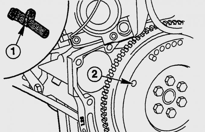
Fig. 8.4. Location of the crankshaft rotation angle sensor (1) and the pulse sector on the flywheel (2)
is installed on all Fiesta engines on the gearbox housing flange and records the exact position and rotation speed of the crankshaft (Fig. 8.4). The sensor signals are important for adjusting the following systems:
- the amount of fuel injected into the engine cylinders;
- ignition timing angle;
- engine crankshaft speed at idle;
- exhaust gas recirculation (EGR).
If the inductive crankshaft angle sensor (CKP) fails, further engine operation is impossible until the sensor is replaced.
Camshaft Position (CMP) Sensor -
is installed in the cylinder head in front of the first cam of the exhaust camshaft. The sensor operates on the inductive principle and controls the fuel injection sequence.
The sensor signal allows the EEC-V-PCM control unit to determine, based on the firing sequence, which cylinder to deliver fuel to and in what sequence.
Oxygen sensor (HO2S) -
is installed in the exhaust manifold and transmits information about the residual oxygen content in the exhaust gases. To reduce the response time to 3 s, the sensor is heated after each cold engine start. The sensor signal affects the adjustment of:
- the amount of fuel injected into the engine cylinders;
- fuel vapor recovery (EVAP).
The oxygen sensor is of great importance for the performance and service life of the catalytic converter.
Differential Pressure Feed Forward Electronic (DPFE) Sensor -
is mounted on a bracket on the front wall of the engine compartment together with the electromagnetic valve of the exhaust gas recirculation system and the electromagnetic valve of the fuel vapor recovery system (EVAP). Based on the signal from the DPFE sensor, the control unit adjusts:
- mass of exhaust gases directed for re-burning;
- electronic vacuum regulator (EVR) position.
Power Steering (PSP) Push Button Switch -
is installed on the right side of the engine compartment in the pressure line of the hydraulic system of the power steering. In the neutral position, the switch is off and is activated only when the pressure in the hydraulic system increases. Based on the signal from the switch, the EEC-V-PCM control unit increases the idle speed. Based on the signal from the DPFE sensor, the control unit adjusts:
- position of the engine idle speed control valve;
- the amount of fuel injected into the engine cylinders;
- ignition timing angle.
Speed Sensor (VSS) -
is installed in the gearbox housing and transmits a signal about the vehicle speed to the control unit. Based on the VSS sensor signal, the control unit corrects:
- engine crankshaft rotation speed when the vehicle is coasting;
- turning off the shift on mountain roads.
Neutral Drive Switch (NDS) -
is installed in the CTX automatic transmission housing. The NDS switch signals limit:
– maximum engine crankshaft speed in neutral gearbox position at 4000 min⁻¹.
Actuators and devices of the EEC-V fuel injection system
Idling Engine Crankshaft Speed Control Valve (IAC) - installed in the air intake pipe.
EGR Vacuum Regulator (EVR) -
mounted on a bracket on the front wall of the engine compartment. The EGR solenoid valve responds to a clock signal from the EEC-V control unit and releases the control vacuum for the EGR valve.
Evaporative Emission (EVAP) Solenoid Valve -
mounted on a bracket on the front wall of the engine compartment. Implements temperature- and load-dependent signals from the EEC-V control unit. When the valve opens, fuel vapors from the activated carbon tank enter the intake tract.
Injectors -
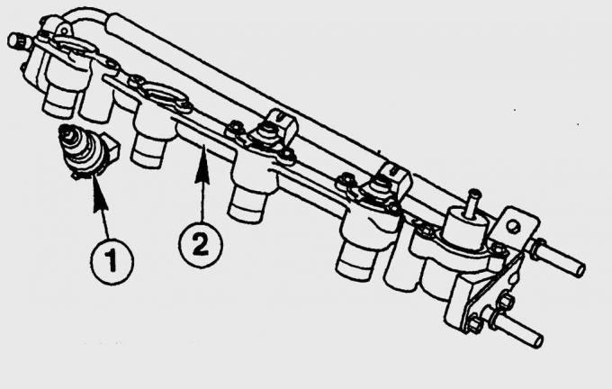
Fig. 8.5. Fuel distribution line (2) with injectors (1)
installed in a common fuel distribution pipeline (Fig. 8.5).
Exhaust gas recirculation system for Zetec-SE engines
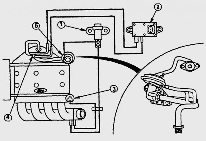
Fig. 8.6. Interrelation of the elements of the exhaust gas recirculation system EGR: 1 – vacuum regulator EGR (EVR); 2 – differential pressure electronic transducer (DPFE); 3 – fuel pressure regulator; 4 – pressure drop section; 5 – EGR valve
The EGR system of the Zetec-SE engines operates in a temperature-dependent manner in the partial load range. When starting the engine and during its warm-up, the coolant temperature is decisive. The DPFE sensor determines the set exhaust pressure difference and from this determines the actual pressure drop. The voltage signal is sent to the EEC-V-PCM and then in a modified form to the EGR vacuum regulator (EVR). Ultimately, the EVR controls the EGR valve, which allows a precisely defined mass of exhaust gas to pass into the intake manifold behind the throttle valve (Fig. 8.6).
Diagnostic elements in the EEC-V fuel injection system
Diagnostic Link Connector (DLC) -
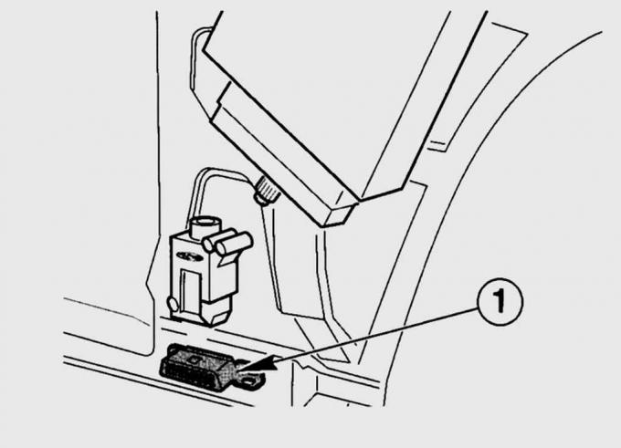
Fig. 8.7. Location of the diagnostic connector (1) at the bottom of the left front pillar
is installed behind the trim at the bottom of the left front pillar (Fig. 8.7). Access to it is opened after removing the protective cover.
Processor unit (CPU).
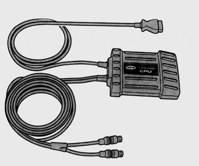
Fig. 8.8. External view of the processor unit (CPU)
If the EEC-V-PCM computer program is not compatible with the diagnostic equipment, the CPU unit replaces it with the FDS 2000 program, which is understandable to the equipment.
[The text was obtained in its entirety from the specified website fordbook]