Contents: Returning excess fuel to the fuel… ↳ Fuel path from the fuel tank to the… ↳ Plunger of the distribution fuel… ↳ Functioning of the plunger of the… ↳ Fuel Shut-Off Solenoid Valve ↳ Centrifugal engine crankshaft speed… ↳ Fuel injection timing adjustment… ↳ A device that facilitates starting a… ↳ Nozzles ↳ Determining a faulty injector ↳ Injector repair ↳
In contrast to combustion engines, the fuel injection systems of diesel engines operate with higher system pressures. The fuel injectors therefore spray fuel at a pressure of 140 bar into the swirl chambers of the Fiesta diesel engine. In order to realize the correspondingly high system pressures, the high-pressure fuel pumps (HPFP) and their peripheral devices are fundamentally different in diesel engines than in combustion engines. The distributor HPFP distributes and injects diesel fuel in defined portions into the swirl chambers of the individual cylinders. From the HPFP, the fuel is supplied directly to the fuel injectors under high pressure.
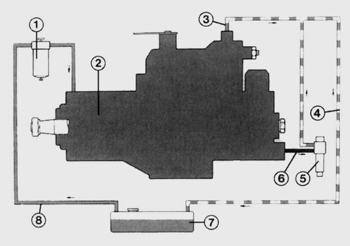
Fig. 8.12. Diagram of the fuel system of a diesel engine: 1 – fuel filter; 2 – high pressure fuel pump; 3 – calibrated hole; 4 – return pipeline; 5 – nozzle; 6 – fuel return pipeline; 7 – fuel tank; 8 – fuel supply pipeline
From the fuel tank, diesel fuel is fed through pipeline 8 (Fig. 8.12) to fuel filter 1. Then, purified diesel fuel is fed to high-pressure fuel pump (HPFP) 2. Excess fuel is returned to the fuel tank through calibrated opening 3 via return pipeline 4. Fuel compressed to high pressure by the HPFP is fed through pipeline 6 to injector 5. A small amount of fuel remaining near the injector nozzle needle also returns to the fuel tank.
Returning excess fuel to the fuel tank
When a diesel engine is running, a significant amount of fuel is pumped, the excess of which is returned to the fuel tank via the return pipeline. The injectors do not inject the fuel supplied to them into the swirl chambers: the excess fuel is used to lubricate the moving parts of the high-pressure fuel pump and injectors. To return the excess fuel, the injectors have special return pipes and are connected to each other by hoses. The fuel returns to the tank from the injector of the first cylinder.
Fuel path from the fuel tank to the injector
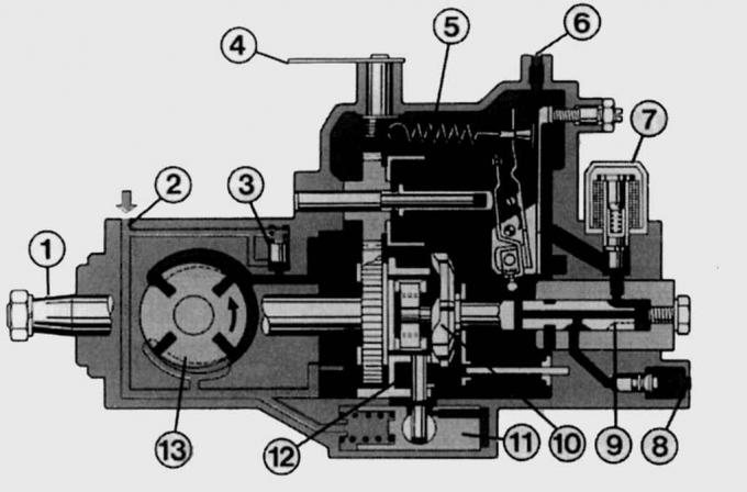
Fig. 8.13. High-pressure fuel pump (HPFP) in section: 1 – drive shaft; 2 – fuel supply; 3 – pressure reducing valve; 4 – manual accelerator control handle; 5 – centrifugal regulator; 6 – fuel return hole; 7 – electromagnetic valve to stop fuel supply; 8 – fuel lines to injectors; 9 – plunger of the distribution fuel injection pump; 10 – cam washer; 11 – fuel injection timing advance clutch (here rotated 90° for better presentation); 12 – roller; 13 – booster vane pump (also rotated 90°)
The fuel-supply vane pump serves to supply fuel from the tank and, together with the pressure control valve, creates pressure in the cavity of the high-pressure fuel pump (HPFP), which increases in direct proportion to the crankshaft speed (Fig. 8.13). The suction fuel pump is located in the housing of the high-pressure fuel pump.
Plunger of the distribution fuel injection pump
The distributor type pump includes only one plunger-sleeve set for feeding all cylinders. The plunger is located in the cavity of the high-pressure fuel pump. In principle, it acts as an ignition distributor in gasoline engines. The design feature of the plunger of the distributor fuel injection pump is a multitude of channels and grooves. The special location of the plunger of the distributor fuel injection pump ensures that it performs two functions. It opens the path of fuel into the cavity and sprays fuel through the nozzles in the swirl chambers of the cylinder head.
The plunger of the distribution fuel pump not only creates the required fuel pressure during its working stroke, but also, while rotating, distributes it to individual outlet openings. The plunger of the distribution fuel pump rotates at a frequency that is half that of the engine crankshaft. During one revolution of the drive shaft, the plunger makes a number of strokes equal to the number of engine cylinders. The drive shaft rotates the cam washer and the plunger to which it is connected. The projections on the cam washer provide axial movement of the plunger and its rotation, i.e. distribution and supply of fuel. The pump continues to supply fuel during the working stroke as long as the plunger outlet opening remains closed. The fuel rushes in the direction of the cylinder that is in the compression stroke. The forward movement of the plunger of the distribution fuel pump simultaneously reduces the volume in front of the piston: now the compressed fuel lifts the injector needle and the fuel is sprayed in the swirl chamber. The fuel pump stops supplying fuel as soon as the outlet hole aligns with the hole in the control sleeve. Then the plunger of the distribution fuel pump, getting into the recess of the cam washer, moves back, and a new portion of fuel gets into its cavity.
Functioning of the plunger of the distribution fuel injection pump
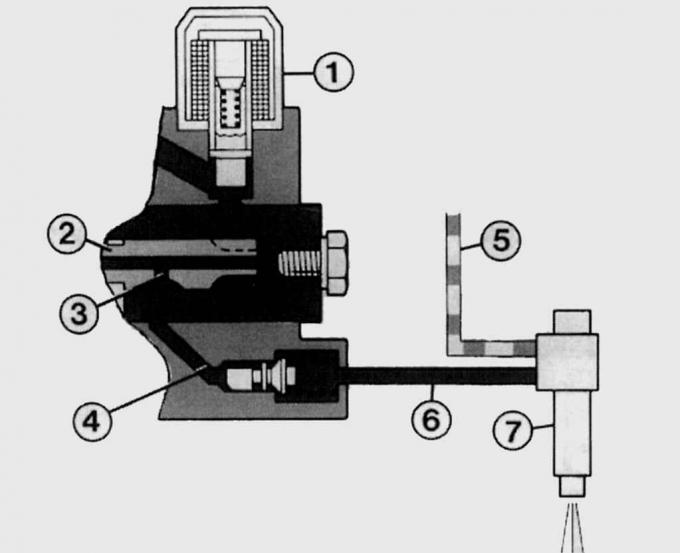
Fig. 8.14. Diagram of the operation of the plunger of the distribution fuel injection pump: 1 - electromagnetic valve for stopping the fuel supply; 2 – plunger of the distribution fuel injection pump; 3 – hole; 4 – channel; 5 – fuel return line to the fuel tank; 6 – high pressure chamber; 7 – nozzle
When the plunger 2 (Fig. 8.14) of the distribution fuel injection pump turns, the filling hole 3 is aligned with the channel 4 through the groove in the plunger. Now the fuel under pressure created by the booster vane pump enters the high-pressure chamber 6 in front of the plunger of the distribution fuel injection pump and fills the entire space. Thus, filling the cavity before fuel compression is complete.
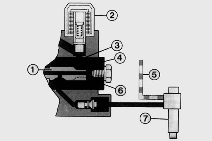
Fig. 8.15. Diagram of the operation of the plunger of the distribution fuel injection pump: 1 – plunger of the distribution fuel injection pump; 2 – electromagnetic valve to stop fuel supply; 3 – distribution channel; 4 – outlet channel; 5 – fuel return line to the fuel tank; 6 – high pressure chamber; 7 – nozzle
After filling, plunger 1 (Fig. 8.15) of the high-pressure distribution pump continues to rotate and the filling hole is closed by the plunger. Then, in the rear part of the high-pressure fuel pump, the projections of the cam washer run onto the rollers and the plunger of the high-pressure distribution pump, fixedly connected to the cam washer, moves forward. The pressure in the high-pressure chamber increases to the required value, and at this time channel 3 is aligned with the channel of the outlet port 4. Then, compressed fuel is supplied to the injector 7 through the high-pressure pipeline. An insignificant amount of the remaining fuel is returned to the fuel tank through the return pipeline 5. The electromagnetic valve for stopping the fuel supply must be open, otherwise the fuel will not be able to get into the high-pressure chamber.
Fuel Shut-Off Solenoid Valve
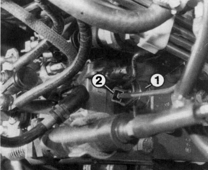
Fig. 8.16. Location of the connector (2) of the electromagnetic valve (1) of the engine stop
Before the fuel enters the filling channel of the plunger of the distribution fuel pump, it passes through the open electromagnetic fuel shut-off valve. As long as voltage is applied to the valve, fuel can pass through it without hindrance. After the voltage is disconnected, electromagnetic valve 1 (Fig. 8.16) closes and shuts off the fuel supply to the plunger of the distribution fuel pump. If it is necessary to turn the engine crankshaft with the starter when checking the valve timing, disconnect connector 2 from the electromagnetic engine shut-off valve to prevent the engine from starting.
Centrifugal engine crankshaft speed controller
To ensure normal operation of the diesel engine in various modes and supply of the required portion of fuel at a strictly defined moment, the distribution fuel injection pumps are equipped with a centrifugal regulator. Its weights move outward under the action of centrifugal force and act on the adjusting valve, which opens the hole in the plunger of the distribution fuel injection pump and thus always adds fuel from the pump cavity.
If the engine speed increases in relation to the accelerator pedal position, the governor closes the orifice and the speed decreases again. When the engine is started, the orifice is fully open and the engine receives the maximum amount of fuel until the idle speed is reached. During engine operation in all modes, the centrifugal governor always compares the engine speed with the accelerator pedal position. Likewise, the centrifugal governor limits the maximum speed, which for the Fiesta diesel engine is 5,350+50 min⁻¹.
Fuel injection timing adjustment clutch
In order to ensure a normal combustion process and reserve the time required to prepare the fuel-air mixture, the start of fuel injection must be performed before the piston reaches the top dead center. For this purpose, a fuel injection advance clutch is used, which shifts the injection to an earlier start and achieves an effect similar to the operation of the ignition advance regulator in internal combustion engines. The fuel injection advance clutch is located in the high-pressure fuel pump housing.
A device that facilitates starting a cold engine
A diesel cold start device performs the same function as an automatic starting device in an internal combustion engine, but that is where the similarities end. The use of a diesel cold start device depends on the air temperature. Without reducing the air flow into the engine cylinders, it shifts the fuel injection timing towards an earlier injection point. This gives the atomized fuel more time to ignite in the compressed air and in the swirl chambers heated by the glow plugs, and the engine starts more reliably and smoothly. In addition, a cold start device slightly increases the idle speed: the engine crankshaft rotates at a frequency of 1100 min⁻¹.
Nozzles
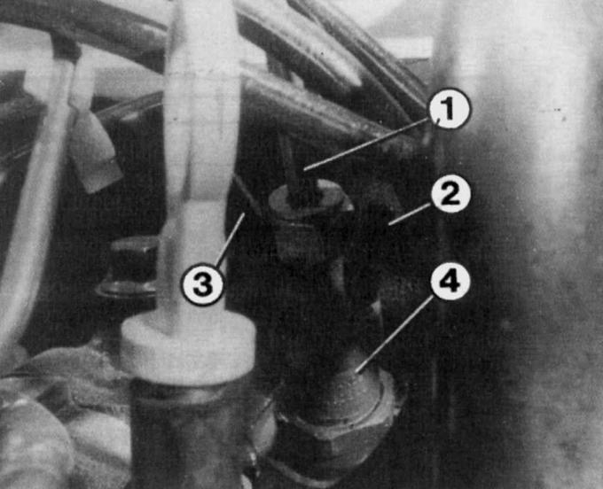
Fig. 8.17. Injector installed on the engine: 1 – injection pressure pipeline; 2 – plug on the fuel return pipe of the 4th cylinder; 3 – fuel return pipeline; 4 – nozzle body
The injectors (Fig. 8.17) are the final element of the fuel injection system of a diesel engine. They spray fuel under high pressure into the swirl chambers of individual cylinders. If the pressure in the system exceeds 143 bar, the spring-loaded needle of the spray nozzle and the nozzle are damaged, causing fuel to leak out of the injection system. To prevent a backflow of burning gases when the nozzle of the injector is still open, the pressure in the high-pressure chamber of the injector must be higher than the pressure in the combustion chamber. This is especially important at the end of injection, when the injection pressure decreases, accompanied by an excessive increase in the pressure of the combustion products. It can only be ensured by careful coordination of the operation of the fuel pump, spray nozzle and needle. The fuel circulating in the fuel system also lubricates and cools all moving parts. Since the total mass of fuel is never injected, excess fuel returns to the fuel tank. The time between the start of injection and ignition is 0.002 s. Therefore, even a minor malfunction in the fuel injection system leads to disruption of the normal operation of the engine. Black smoke from the exhaust pipe and noisy operation of the diesel engine indicate the need to check and adjust the fuel injection system.
Determining a faulty injector
You can determine whether an injector is not working as follows. Start the engine and let it idle. Loosen the union nuts securing the high-pressure pipes to the injectors one by one. When you loosen the nut on a working injector, the engine crankshaft speed should decrease noticeably. If the engine crankshaft speed does not change when you loosen the nut, then the injector being tested is faulty.
You can also identify faulty injectors by the following symptoms:
- constantly burning glow plug tip;
- constant black smoke from the exhaust pipe;
- increased fuel consumption;
- frequent engine overheating;
- harsh noises during fuel combustion;
- reduction in power.
If you have any of the listed signs of a malfunction of the diesel engine of the Fiesta, visit a car repair shop to get a qualified opinion on the presence of a malfunction and measures to eliminate it.
Injector repair
Standard injector bodies include a spray nozzle and a shut-off needle. The injector needle moves freely within the spray guide channel and at the same time provides sealing under high injection pressure. There is a conical seal at the bottom of the needle. The injector spring presses the needle against the correspondingly shaped surface of the spray nozzle when the injector is in the closed position. The conical surfaces of the spray nozzle and needle provide contact with high specific pressure and effective sealing. The injector opens when the fuel pressure force on the sealing surface exceeds the force of the injector spring. It will remain open until the pressure in the system decreases to a value below the opening pressure.
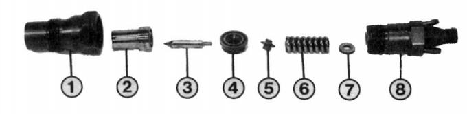
Fig. 8.18. Nozzle parts: 1 – body; 2 – sprayer body; 3 – spray needle; 4 – plug-in block of the nozzle body; 5 – stop bolt; 6 – injector pressure spring; 7 – installation disk; 8 – upper part of the body
Without special equipment, a worn-out injector can only be identified visually by external local damage or heavy contamination. However, injectors usually wear out in the inner part of the atomizer, the atomizer needle and the pressure spring. Special equipment must be used to adjust the measurement and injection pressure, i.e. change the force of the pressure spring. In most cases, it is better to replace the faulty injector. If you decide to disassemble the injector, do not leave the parts open on the workbench longer than necessary, since the precision-machined surfaces of the atomizer needle and housing are extremely sensitive to dust or rust. To disassemble the injector, unscrew its upper part from the housing and remove all internal parts of the injector (Fig. 8.18). The tightening torque for fastening the upper part of the injector to the housing is 80 N·m.
(A copy of the article is available on the website fordbook)