Contents: Upper intake manifold and throttle… ↳ Additional air valve ↳ Throttle Position Sensor (TP) ↳ Fuel rail assembly ↳ Fuel injectors ↳
Upper intake manifold and throttle body
Note: This procedure will replace the upper/lower intake manifold gasket and service the fuel rail assembly components. The subsequent procedure will replace the throttle body/upper intake manifold gasket.
Disassembly
1. Disconnect the negative battery cable.
2. Remove the air cleaner connecting hose (see section 8)
3. Disconnect the electrical connectors of the secondary air valve, throttle position sensor and EGR position sensor (see figures).
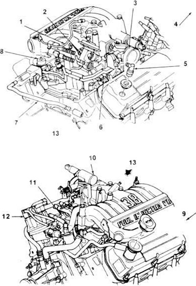
14.3, a. Basic elements of the electronic fuel injection (EFI) system used in 3.8LV6 engines.
1. Vacuum line connector.
2. EGR valve.
3. Throttle body.
4. Front of the engine.
5. PCV valve.
6. Fuel injector.
7. Crankcase ventilation tube.
8. Fuel pressure regulator.
9. Front of the engine.
10. Additional air throttle valve.
11. Fuel injector.
12. Distributor with cover assembly.
13. View A.
4. Disconnect the throttle cable and downshift cable from the throttle connection (see section 9).
5. Carefully mark and then disconnect the vacuum lines from their inputs (branches), as well as the EGR valve, fuel pressure regulator and the two tubes from their corresponding ends on the throttle body.
6. Disconnect the PCV hose from the fitting located at the rear of the upper manifold.
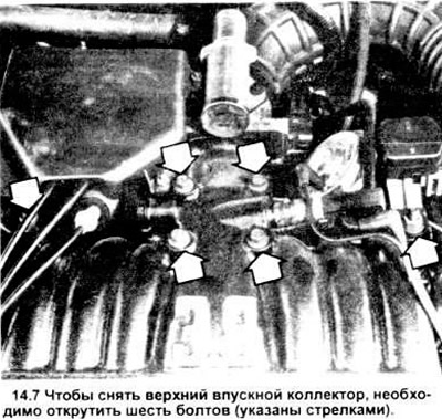
7. Remove the six upper intake manifold mounting bolts (see illustration).
8. Remove the upper manifold together with the throttle body from the lower intake manifold.
9. Remove and discard the old gasket.
Installation
10. Clean and inspect the upper and lower intake manifold gasket surfaces. When scraping off gasket residue, be careful not to damage the contact surfaces.
11. Place a new gasket on the sealing surface of the lower intake manifold. You can use studs as guide pins.
12. While holding the gasket in place with studs, install the upper intake manifold with throttle body onto the lower manifold.
Note: If the manifold does not have guide studs, make sure the gasket does not move when installing the top section with the throttle body onto the manifold.
13. Install the six upper intake manifold mounting bolts and tighten them to the specified torque.
14. Installation is carried out in reverse order.
Throttle body
Note: If you need to service or disassemble the throttle body, and if you are replacing the gasket between the body and the upper intake manifold, see the following procedure. If you are going to work on any component installed deeper than the upper intake manifold, use the above sequence (there is no need to separate the throttle body and upper intake manifold; they can be removed as one unit).
Disassembly
15. Disconnect the negative battery cable.
16. Remove the air cleaner housing inlet pipe (see section 9)
17. Disconnect the electrical connectors from the throttle position sensor and the secondary air crusher valve (see below).
18. Disconnect the throttle cable, cruise control cable (if equipped) and transmission downshift cable (see section 9).
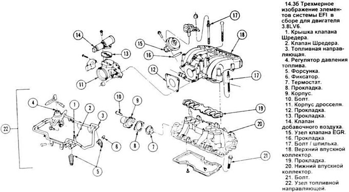
19. Unscrew the four nuts securing the throttle body (see Figure 14.36). Remove the throttle body.
20. Remove and discard the gasket located between the throttle body and the upper intake manifold.
Installation
21. Clean the mating surfaces. When cleaning, be especially careful not to damage the gasket surface and to prevent debris from getting inside the manifold.
22. Install the throttle body gasket onto the four upper intake manifold studs.
23. Tighten the throttle body to manifold mounting nuts to the specified torque.
24. Installation is carried out in the reverse order of disassembly.
Additional air valve
Disassembly
25. Pull out the electrical connector of the additional air valve (see figure).
26. Unscrew both bolts securing the valve.
27. Remove the valve itself and its gasket.
Installation
28. Clean the mating surfaces of the gasket.
Note: When cleaning, be especially careful not to damage the valve, throttle body gasket surface, or drop debris into the throttle body.
29. Installation is carried out in the reverse order of disassembly.
Throttle Position Sensor (TP)
Disassembly
30. Pull out the electrical connector of the TP sensor (see Figure 14.25).
31. Make a mark running from the end of the sensor to the throttle body to ensure the sensor is positioned correctly when installed.
32. Remove the two throttle position sensor retaining screws.
33. Remove the TP sensor.
Installation
34. Perform in the reverse order of disassembly. Check the reliability of tightening the screws of the TP sensor.
Fuel rail assembly
Disassembly
35. Unscrew the fuel filler cap.
36. Relieve the pressure in the fuel system (see section 2).
37. Disconnect the cable from the negative battery terminal.
38. Remove the upper intake manifold and throttle body assembly (see above).
39. Remove the fuel injector electrical connectors.
40. Disconnect the fuel adapter hose from the guide assembly using the Ford special tool for filler and spring connections (ND87L-9280-A or B) or its equivalent.
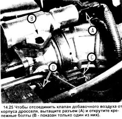
To remove the throttle position sensor, pull out the connector (C) and loosen the retaining screws (D - only one shown).
41. Remove the four bolts (two on each side) securing the fuel rail assembly (see illustration).
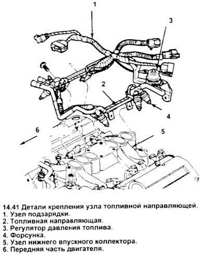
42. Carefully separate the guide and fuel injectors and remove them.
Note: You may find it easier to simply remove the guide from the lower intake manifold without removing the injectors, and then separate the injectors from the guide (see below).
Installation
43. The fuel rail can be installed in two ways.
a) first, place the injectors one by one into the lower intake manifold (see below), then place the fuel rail over them and push it onto the injectors until it fits securely.
b) first, place the injectors in the guide, correctly position the guide with the injectors relative to the lower intake manifold, then carefully insert the injectors into their sockets in the lower intake manifold.
44. Attach the fuel rail assembly to the lower intake manifold with four bolts and tighten securely.
45. Installation is carried out in the reverse order of disassembly.
Fuel injectors
Removal
46. Remove the fuel rail assembly (see above).
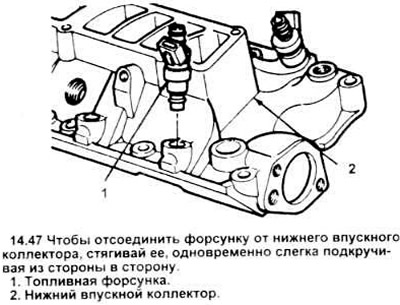
47. Having pulled the guide itself separately from the injectors, grasp each injector by the body and pull them out, slightly rocking them from side to side (see figure). If the injectors were pulled out together with the guide, then carefully pull the injectors out along one of the guides, rocking them from side to side (see figure 13.39).
48. After marking the position of the sealing rings on the injectors, remove and discard the rings (see Figure 13.48).
49. Check the washer and the plastic cap covering the spray nozzle of each injector (see picture), there may be signs of damage. Replace if necessary.
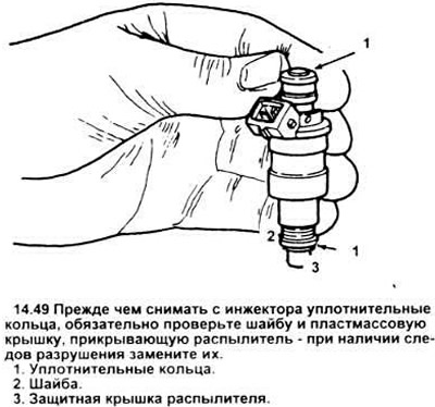
Note: If the "cap" is missing, look for it in the intake manifold.
Installation
50. Lubricate the new sealing rings with light oil (ESE - M2C39 or similar) and install them on the ends of each injector.
Note: Do not use silicone grease as it will clog the injectors.
51. Using a gentle pushing and turning motion, install the injectors either into the lower intake manifold or into the fuel rail assembly (use whichever method seems easiest to you).
52. Install the fuel rail assembly as described above.
53. Installation is carried out in the reverse order of disassembly.
The original text is provided on an online resource: FORDBOOK.RU