Contents: Replacing the headlight corrector… ↳ Removal and installation the watch ↳ Removal and installation the… ↳ Removal and installation the horn ↳ Removal and installation the horn… ↳ Removal and installation seat heater… ↳ Removal and installation the… ↳
Replacing the headlight corrector motor
The headlight corrector motor is installed on the rear side of the headlight and is secured using a bayonet clamp.
1. Remove the electrical connector from the headlight range control motor.
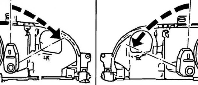
2. Press the corrector motor in the direction of the headlight and in this position turn the motor clockwise for the right headlight or counterclockwise for the left headlight.
3. Press the lever of the locking installation shaft through the hole in the headlight housing and remove the corrector motor from the headlight.
4. Installation is carried out in the reverse order of removal.
Removal and installation the watch
1. Remove the upper console.
2. To remove the upper console, remove the interior light and the sunroof opening handle, unscrew the two screws securing the front part of the console, lower the front part of the console down and move it back.
3. Remove the back cover of the watch, having first unscrewed two screws.
4. Unscrew the two mounting screws and remove the watch.
5. Install the clock on the console.
6. Install the back cover of the watch and then the top console.
Removal and installation the cigarette lighter
1. Remove the ground wire from the battery.
Front cigarette lighter
2. On models with a higher trim level, remove the center console trim from the radio to access the cigarette lighter.
3. On models with standard interior trim, remove the radio.
4. Disconnect the wires from the cigarette lighter and remove it from the illuminated ring.
Rear cigarette lighter
5. Remove the heater control knob.
6. Remove the rear center console panel after unscrewing the two mounting screws.
7. Disconnect the wires from the cigarette lighter and remove it from the illuminated ring.
8. Installation is carried out in the reverse order of removal.
Removal and installation the horn
The car has two sound signals. The high-pitched sound signal is installed to the right of the radiator and is accessible from the engine compartment. The low-pitched sound signal is installed below and to the left of the radiator and is accessible from below the engine compartment.
1. Unscrew the fastening nut or bolt and remove the vibration damping washer.
2. Remove the electrical connectors and remove the horn.
3. Installation is carried out in the reverse order of removal.
Removal and installation the horn switch, contact rings and brushes
1. Remove the ground wire from the battery.
2. Remove the steering wheel center trim.
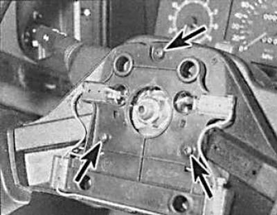
3. Unscrew the three screws (indicated by arrows) securing the horn switch bracket.
4. Remove the electrical connector and take out the horn switch bracket.
5. Remove the steering wheel.
6. Bend the ears that secure the contact rings to the bottom of the steering wheel, disconnect them from the bracket and remove the contact rings.
7. Remove the upper and lower steering column covers.
8. Disconnect the wires from the horn brushes.
9. Carefully push out the brush block with a screwdriver inserted under the bottom edge of the block.
10. Installation is carried out in the reverse order of removal.
Removal and installation seat heater elements
1. Remove the seat.
2. Remove the seat upholstery.
3. Mark the direction of the heating element, then remove the wire clips and tape securing the element to the seat.
4. Install the clamps on the new element.
5. Install the new heating element with the front side facing the cushion foam. Secure the heating element with wire clips and tape. Check that the heating element deflects when a load is applied to the seat.
6. Install the seat upholstery.
7. Install the seat.
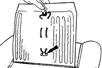
8. The regulator (arrow) should be facing the front side towards the foam of the cushion.
Removal and installation the ignition switch contact group
1. Remove the ground wire from the battery.
2. Remove the upper and lower steering column covers, first unscrewing the six mounting screws.
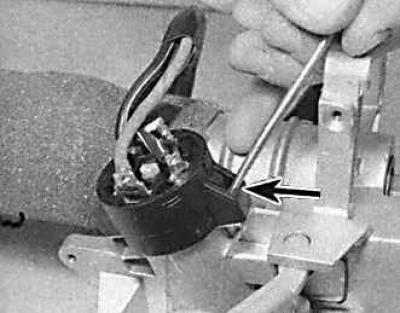
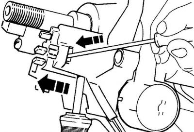
3. Release the ignition switch contact group (arrow) by pressing the two fastening lugs.
4. When installing, check that the slot in the center of the ignition switch contact group is aligned with the protrusion on the lock.
5. Connect the ignition switch contact group and press it into place until the mounting ears snap into place.
6. Connect the ground wire to the battery and check the functionality of the ignition switch contact group, then install the steering column covers.
(This publication was borrowed from the website FordBook)