General description
1. The intake air temperature control system monitors the air temperature, then adjusts the intake air temperature to a range of 21-41 degrees Celsius (70-105 degrees Fahrenheit) by mixing warm and cold air. This reduces the enrichment of the air-fuel mixture for the CFI system, which in turn reduces emissions and improves vehicle drivability.
2. Two fresh air inlets are used - one cold and one hot. The balance between them is set by vacuum control of the intake manifold, a vacuum temperature switch and a time delay valve. The vacuum motor regulating the operation of the air cleaner heat-conducting valve is controlled by a vacuum switch.
3. When the outside temperature is low, the air heated by the exhaust manifold is conducted through the outside hot air bypass and into the air cleaner. This provides the CFI system with warm air, which results in better handling and faster heating. When the outside temperature rises, the heat transfer valve is closed by the vacuum motor, and the air cleaner conducts air through the cold air tube. The result is a constant air intake temperature.
4. The vacuum temperature switch (see figure), mounted on the air cleaner housing, controls the temperature of the intake air heated by the exhaust manifold.
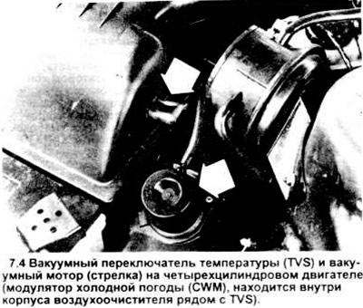
The vacuum temperature switch has a bimetallic disc that self-adjusts to one of two positions depending on the temperature. One position of the disc allows vacuum to flow to the motor through the hose, the other blocks it.
5. The operation of the vacuum motor itself is controlled by a cold weather modulator (CWM) mounted next to the vacuum temperature switch inside the air cleaner housing (see figure); this modulator sets the motor to one of a series of graduated positions, ranging from "fully open" to "fully closed".
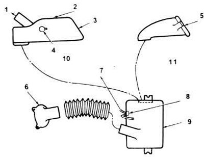
7.5 Cold Weather Modulator Location.
1. To the heating pipe.
2 Pipeline and valve assembly.
3. Fresh air.
4. Vacuum motor.
5. Fresh air.
6. Fuel injection unit.
7. To the vacuum motor (pipeline and valve).
8. Cold Weather Modulator (CWM) (2.5L CFI only).
9. Air cleaner unit.
10. 2.5L CFI Tauras/Sable.
11. 3.0L EFI Tauras/Sable.
Examination
Note: Make sure the engine is cool before starting testing.
6. Always check the vacuum source and the integrity of the hoses between the source and the vacuum motor before beginning the suggested testing.
7. Apply the parking brake and block the wheels.
8. Disconnect, but do not remove, the air cleaner housing and element (see chapter 4).
9. Turn the air cleaner housing so that the vacuum motor door is visible. The door should be open.
Make sure it is not stuck open or closed by trying to move it by hand. If there is rust, the door should be cleaned and oiled. If the door does not work properly after servicing, replace it.
10. If the door is OK but the vacuum motor still does not function properly, carefully inspect the hose leading to it - it may be leaking. Check the vacuum source, including the bimetal sensor and the time delay valve. If there is no leak, replace the vacuum motor (see paragraph 26).
11. Start the engine. If the manifold flap has moved or is moving toward the "heat" position (blocking fresh air), proceed to paragraph 15.
12. If the flap remains in the "heat on" position (blocking the warm air), close the outlet from the bimetallic sensor with your finger. The pipeline flap should quickly move to the "heat" position. If this does not happen, turn off the engine and replace the vacuum motor (see paragraph 26). Perform the operations on the new motor specified in this paragraph.
13. With the engine off, cool the bimetallic sensor and cold weather modulator by blowing compressed air on them.
14. Start the engine again. The manifold door should move to the "heat" position. If this does not happen, or it only moves partially, replace the TVS (see paragraph 18).
15. Start and warm up the engine quickly (less than 15 seconds). The pipeline door should move to the "heating" position.
16. Turn off the engine, watch the door. It should remain in the "heating" position for at least two minutes.
17. If this does not happen, replace the CWM (see paragraph 23) and repeat the operations of this paragraph again after the CWM and bimetallic sensor have cooled down.
Replacement of elements
Temperature Vacuum Switch (TVS)
18. Tag and disconnect both vacuum hoses from the TVS assembly (one goes from the vacuum source to the manifold and the other goes to the vacuum motor under the air cleaner housing).
19. Remove the air cleaner housing cover (see chapter 1 or 4 if necessary).
20. Using a screwdriver, remove the TVS clamp.
21. Remove TVS.
22. Install in reverse order.
Cold Weather Modulator
23. Disconnect the air cleaner housing assembly (see chapters 1 and 4) and turn it over.
24. Locate the CWM, disconnect both vacuum hoses and remove the modulator.
25. Install in reverse order.
Vacuum motor
26. Disconnect the air cleaner housing assembly (see chapters 1 and 4) and turn it over.
27. Locate the vacuum motor.
28. Disconnect the vacuum hose and drill out the motor mounting rivet.
29. Remove the motor.
30. Install in reverse order.
[For more information, please visit the specified website: FORDBOOK.ru]