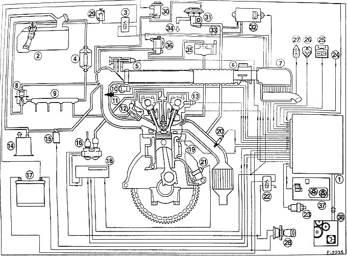
1 - EEC IV control unit Location in the passenger footwell next to the driver, behind the glove compartment
2 - fuel pump
3 - fuel pump relay
4 - fuel filter
5 - Idle speed control valve (ISC)
6 - Mass Air Flow (MAF) meter
7 - air filter
8 - fuel pressure regulator
9 - fuel manifold
10 - throttle position sensor
11 - intake air temperature sensor
12 - valve injector
13 - camshaft position sensor
14 - container with activated carbon
15 - electromagnetic cleaning valve
16 - DIS ignition coil
17 - battery
18 - EDIS-4 module
19 - coolant temperature sensor
20 - oxygen sensor
21 - Crankshaft speed/position sensor
22 - Power supply system relay
23 - hydraulic switch of the power steering mechanism
24 - air conditioning compressor clutch
25 - octane number adjustment service connector
26 - plug connector of the self-diagnostic system
27 - diagnostic connector for FDS 2000 diagnostic system
28 - ignition and starter switch
29 - safety switch
30 - electronic vacuum regulator
31 - exhaust gas recirculation (EG) valve
32 - differential pressure transducer
33 - place of measuring the pressure difference
34 - to the intake manifold
35 - Pulse air filter / valve box
36 - electromagnetic valve controlled using air flow pulses
37 - Air conditioning system/engine cooling fan switch unit
38 - Automatic transmission control unit