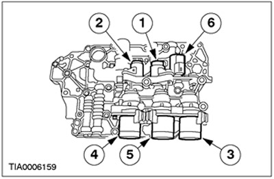
Location of the transmission solenoid in the block with the drive axle
| Position | Name |
| 1 | SSA |
| 2 | SSB |
| 3 | SSC |
| 4 | SSD |
| 5 | SSE |
| 6 | PCA |
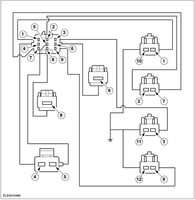
Internal connectors of the electrical wiring of the gearbox in the block with the driving axle
| Pin | Circuit function | Connector color |
| 1 | SSE | Green color |
| 2 | PCA | Black color |
| 3 | SSC | WHITE COLOR |
| 4 | TFT SIGRTN | Black color |
| 5 | TFT | Black color |
| 6 | SSA | WHITE COLOR |
| 7 | PCA | Black color |
| 8 | SSB | Black color |
| 9 | SSD | BLUE COLOR |
| 10 | "WEIGHT" SSE | green color |
| 11 | "WEIGHT" SSC | WHITE COLOR |
| 12 | "WEIGHT" SSD | BLUE COLOR |
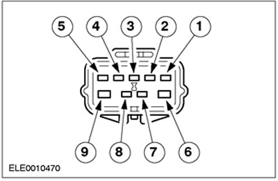
Transmission wiring connector in block with drive axle
| Pin number | EEC pin number | Circuit function |
| 1 | 102 | SSE |
| 2 | 44 | PCA |
| 3 | 82 | SSC |
| 4 | 91 | TFT signal return |
| 5 | 37 | TFT |
| 6 | 73 | SSA |
| 7 | 81 | PCA |
| 8 | 1 | SSB |
| 9 | 99 | SSD |
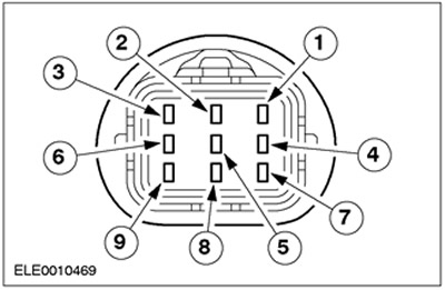
Transmission Range Sensor Wiring Harness Connector (TR)
| Pin number | EEC pin number | Circuit function |
| 1 | - | VPWR |
| 2 | 11 | Movement position |
| 3 | 7 | 1st position |
| 4 | 4 | Reverse position |
| 5 | 64 | Parking position |
| 6 | - | Launch system |
| 7 | 8 | 2nd position |
| 8 | 64 | Parking position |
| 9 | - | Launch system |
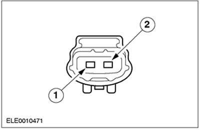
Output Shaft Speed Sensor Wiring Harness Connector (OSS)
| Pin number | Circuit function |
| 1 | Secondary shaft speed sensor (OSS) |
| 2 | Signal return |
Turbine Shaft Speed Sensor Wiring Harness Connector (TSS)
| Pin number | Circuit function |
| 1 | Turbine shaft speed sensor (TSS) |
| 2 | Signal return |
Transmission range sensor diagnostic table (TR)
| Selector position | TR probe pins Element side | Expected value. |
| PARK | 1 and 2, 3 and 4 | Less than 5 ohm |
| REVERSE | 3 and 5 | Less than 5 ohm |
| NEUTRAL | 1 and 2, 3 and 6 | Less than 5 ohm |
| DRIVE | 3 and 7 | Less than 5 ohm |
| 2 | 3 and 8 | Less than 5 ohm |
| 1 | 3 and 9 | Less than 5 ohm |
Link to this page in different formats
HTMLTextBB Code
No comments yet

Visitor comments