Switching control
When a switch is performed, certain elements are released while others are put into operation. Ideally, this process occurs simultaneously (synchronously), to avoid jerking when switching.
The duration of the switching process must remain within the stipulated time range.
With conventional shift control, the increase and decrease in pressure in the shift elements is adjusted and determined for ideal conditions (for synchronous switching). Because there is no way to influence the control in case of varying degrees of wear of the shift elements, in cases where the gearbox has worked out a very long resource, it is possible that the increase and decrease in pressure will no longer occur synchronously.
The result of a premature decrease in pressure in the switched off element is an undesirable increase in the speed of the turbine shaft, because the included element cannot transmit the primary torque.
The result of the delayed decrease in pressure in the switched off element is an undesirable decrease in the speed of the turbine shaft, since both switching elements transmit torque. In this case, the torque is transmitted to the gearbox housing using an internal lock.
In both cases, a twitch will be felt when switching.
In addition, wear in the switching elements leads to an increase in the duration of the switching procedure. Therefore, as the life of the gearbox increases (increase in mileage) switching becomes longer and longer.
Switchover control using ESSC
The 4F27E automatic transmission uses electronically controlled shifting (ESSC).
The ESSC controls shift performance and is able to compensate for shift element wear throughout the life of the transmission.
This is possible because the switching elements are operated by modulating valves.
The system monitors shift timing and shift timing.
If the PCM detects a deviation from the stored values for the switching time and timing of the switching process, the increase or decrease in pressure will be adjusted accordingly.
Throttle position sensor (TR)
The TP sensor is located on the throttle body. It provides the PCM with throttle position information. It also determines how fast the throttle is applied. The PCM uses these signals to perform, among other things, the following functions:
- determining the switching order,
- pressure control in the main line,
- torque converter lock-up clutch control,
- for the function to work "Kickdown" (shifting gears by pressing the accelerator pedal).
In the absence of a TP signal, the engine control uses the MAF and IAT sensor signals as substitutes. Main line pressure builds up and hard shifting may occur.
Mass air flow sensor (MAF) and air intake temperature sensor (IAT)
The MAF sensor is located between the air filter housing and the intake hose to the throttle body. The IAT sensor is built into the MAF sensor housing. The MAF sensor, together with the IAT sensor, provides the PCM with a primary load signal. The PCM uses these signals to perform, among other things, the following functions:
- switching control,
- pressure control in the main line.
If the MAF sensor fails, the TP sensor signal is used as a substitute.
Crankshaft position sensor (TFR)
The TFR sensor is located on the engine/gearbox flange. The CKP sensor is an inductive sensor that provides the PCM with information about engine speed and crankshaft position. The signal is used to perform, among other things, the following functions:
- torque converter lock-up clutch control,
- torque converter slip test,
- pressure control in the main line.
There is no substitute signal for the TFR sensor. If there is no CKP sensor signal, the engine stops.
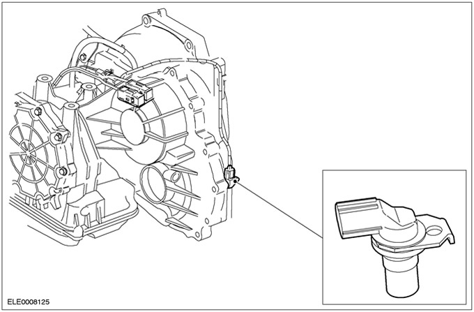
Turbine shaft speed sensor (TSS)
The TSS sensor is located in the gearbox housing above the gearbox input shaft. The TSS sensor is an inductive sensor that senses the speed of the gearbox input shaft. The signal is used to perform the following functions:
- switching control,
- torque converter lock-up clutch control,
- torque converter slip test.
If the TSS sensor fails, the input shaft speed sensor signal is used as a substitute (OSS).
Secondary shaft speed sensor (OSS)
The OSS sensor is located in the gearbox housing above the rotor in the differential. The OSS sensor is an inductive sensor that uses a rotor in the differential to sense the vehicle's speed. The signal is used to perform, among other things, the following functions:
- determining the switching order,
- supplying an input signal about the speed of the vehicle to the PCM.
If the OSS sensor fails, the TSS sensor signal is used as a substitute.
Transmission range sensor (TR)
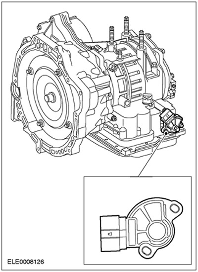
The TR sensor is located on the hand shaft on the gearbox housing.
When moving the hand shaft using the manual select lever cable, the engagement pin in the inner ring of the TR sensor moves through various positions. Signals are sent to the PCM, reversing lights and starter relay.
NOTE: Proper TR sensor operation is only guaranteed when the manual select lever cable is properly adjusted.
TR sensor signals are used to perform the following functions:
- recognition of the position of the lever of manual gear selection
- starter relay activation
- turning on the reversing lights
There is no substitute signal for the TR sensor. In the event of a break in the electrical circuit, the car will not be able to start.
Stoplight switch
Brake Pedal Position Switch (WRR) located on the brake pedal bracket. It turns on the brake lights and informs the PCM EEC V that the brakes have been applied. The brake light switch signal is used by the PCM to perform the following functions:
- releasing the locking clutch of the torque converter when pressing the brake pedal,
- deactivation of the blocking of the shift of the manual gear selector lever when the brake pedal is pressed in the position "R".
There is no substitute signal for the BPP switch. In the event of a break in the electrical circuit of the BPP switch, the manual gear selector lever cannot be removed from the position "R".
Transmission fluid temperature sensor (TFT)
The TFT sensor is located on the internal wiring harness to the oil sump solenoid valves. This is a resistor that measures the temperature of the transmission fluid. The transmission fluid temperature information is used by the PCM to perform the following functions:
- the engagement of the torque converter clutch is not allowed until the temperature of the transmission fluid reaches a certain temperature;
- in conditions of extremely low negative temperature, engagement of 4th gear is not allowed until normal operating temperature is reached;
- if the transmission fluid temperature is too high, a preset shift curve is selected and the torque converter lock-up clutch is locked in position "2", "3" or"4" transmission, the transmission warning light comes on. There is no substitute signal for the TFT sensor.
Overdrive switch (O/D)
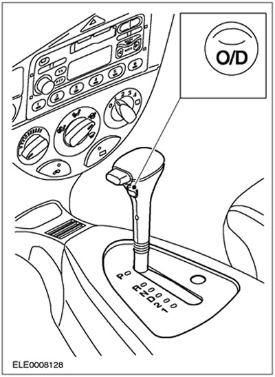
The O/D switch sends a signal to the PCM to select or disable 4th gear selection when the manual gear lever is in the "D". The O/D switch signal is used to perform the following functions:
- as an input to transmit the desire of the PCM driver,
- to display the desire of the driver using the O/D indicator lamp on the instrument panel.
There is no substitute signal for the O/D switch. If it is defective, it is always possible to shift into 4th gear with the manual gear lever in position "D".
Shift lock solenoid for manual gear selector
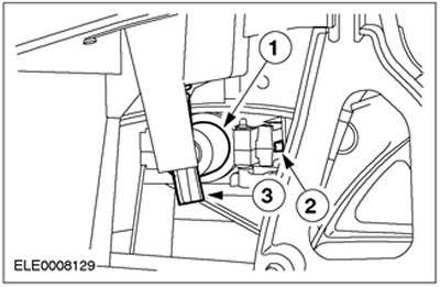
| Pos. | Spare Part No | Name |
| 1 | - | Electromagnet |
| 2 | - | Locking pin |
| 3 | - | Manual release mechanism |
When the ignition is turned on, the manual shift lock solenoid is activated by depressing the brake pedal (stoplight switch signal). This causes the locking pin to retract and the manual gear selector lever can thus be moved out of position "R".
Replacement function
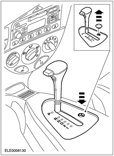
If the signal from the brake is not received or is incorrect due to incorrect functioning, manual release of the blocking is possible.
To do this, remove the cover of the release mechanism and insert a suitable object (ignition) into the hole so that the manual gear selector lever can be moved out of position "R".
NOTE: If the range "R" is selected again, the manual gear lever will be locked again.
Air conditioning
If the PCM registers a signal "Kickdown" (shifting gears by pressing the accelerator pedal) (WOT, throttle open 95%), the air conditioning system is turned off for a maximum of 15 seconds.
Starter Interlock Relay
The relay prevents the engine from starting when the manual gear selector is in the "R", "D", "2" or "1".
The relay receives information about the position of the gear lever directly from the TR sensor.
Ignition key lock solenoid
The solenoid is built into the ignition switch. With the gear selector in position "R", the ground circuit of the electromagnet is broken. The locking pin is not locked into the ignition switch.
In all other positions of the manual gear lever, the solenoid ground circuit is closed and the locking pin is locked in the ignition switch.
When the manual gear selector is in a position other than "R", it is not possible to remove the key from the ignition switch.
O/D indicator lamp
The O/D indicator is a green indicator located on the instrument panel.
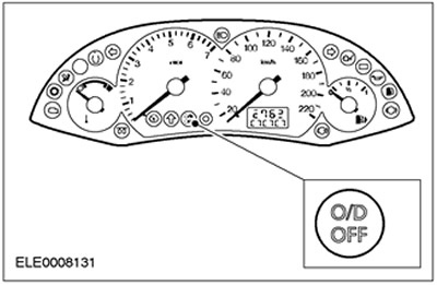
It informs the driver that the transmission control is blocking shifting to 4th gear.
Control lamp of the power unit
The Powertrain Warning Light is an orange light located on the instrument panel.
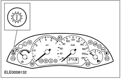
Turning it on informs the driver that the transmission control has switched to an emergency operating program, or that the transmission fluid temperature is too high.
Visitor comments