Contents: Checking the crankshaft speed in… ↳ Checking the pressure in the main… ↳ Checking the maximum crankshaft speed ↳ Table of maximum engine crankshaft… ↳ Engine Crankshaft Speed Limit… ↳ Air pressure tests ↳
Special tool
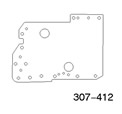 | Air Pressure Test Panel and Gasket 307-412 |
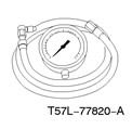 | Pressure gauge 307-132 (17-014) |
To assist the technician in diagnosing the hydraulic and mechanical parts of the transmission in the block with the driving axle, special tests have been developed.
Checking the crankshaft speed in idle mode
Refer to PCED for information on diagnosing and testing the idle speed.
Checking the pressure in the main line
CAUTION: Perform the line pressure test before the limit speed test. If the line pressure is low at the limit speed, do not perform the limit speed test, otherwise the transaxle damage will be aggravated. Do not hold the throttle fully open for more than five seconds in any gear.
NOTE: Some sensor failure may cause PC, FMEM to operate abnormally. Make sure to perform self-test and electrical repair, or the test results may be incorrect.
This check verifies that the line pressure is within specification.
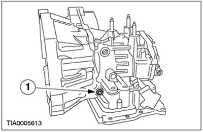
1. Connect the pressure gauge to a special branch of the line to check the pressure.
2. Start the engine and check the line pressure. To determine if the line pressure is within the normal range, refer to the table below, "Line Pressure".
3. If the line pressure is not within specification, refer to the "Line Pressure Diagnostic Chart" for information on line pressure related problems.
| Pos. | Spare Part No | Name |
| 1 | - | Special branch for checking pressure in the main line |
Line pressure table
|
Transmission |
Range |
Idle mode |
Limit mode |
||
|
kPa |
PSI |
kPa |
PSI |
||
|
4F27E |
P, N |
345-450 |
50-65 |
1240-1450 |
180-210 |
|
R |
450-585 |
65-85 |
1930-2310 |
280-335 |
|
|
D, 2, 1 |
345-450 |
50-65 |
1240-1450 |
180-210 |
|
Line Pressure Diagnostic Table
| Test results | Possible reason |
| Low pressure in all ranges | Worn out pump |
| Low pressure in all ranges | Fluid leak from pump, main control valve block or transmission housing in block with drive axle |
| Low pressure in all ranges | The pressure control solenoid valve is not working. |
| Low pressure in all ranges | The electromagnetic control valve is stuck. |
| Low pressure only in ranges D, 2 and 1 | Fluid leak from forward clutch hydraulic circuit |
| Low pressure in range 2 | Fluid leak from the hydraulic circuit of the intermediate/overdrive band brake |
| Low pressure only in ranges 1 and R | Fluid leak from low/reverse clutch hydraulic circuit |
| Low pressure only in R range | Fluid leak from the reverse clutch hydraulic circuit |
| High pressure in all ranges | The pressure control solenoid valve is not working or the wiring harness is broken. |
| High pressure in all ranges | Pressure regulator valve sticking |
| High pressure in all ranges | PCM not working. |
Checking the maximum crankshaft speed
During this test, the following elements and parameters are checked:
- torque converter clutches,
- forward motion clutches,
- low gear single acting clutch assemblies,
- dynamic characteristics of the engine.
WARNING: When performing each extreme test, the parking brake must be fully applied.
CAUTION: Always perform a line pressure test before checking the engine speed limit. If the line pressure is low at the engine speed limit, do not perform the line speed limit test, otherwise the transaxle damage will be aggravated.
NOTE: The maximum speed check should be performed with the engine and transaxle at normal operating temperature.
1. Connect the tachometer to the engine.
CAUTION: After checking each of the following ranges: D, 2, 1, and R, move the shift lever to the N (NEUTRAL) position and run the engine at 1000 rpm for approximately 15 seconds to allow the torque converter to cool before checking the next range.
CAUTION: In any gear, do not hold the throttle in the fully open position for more than five seconds.
CAUTION: If the engine speed indicated by the tachometer exceeds the maximum specified value, release the accelerator pedal immediately. Exceeding this value indicates that the clutch or band brake is slipping.
NOTE: Continued use of this procedure may cause DTC P0712, P1783 to set. After performing the Overspeed Check, perform an OBD Check and clear the DTCs from memory.
2. Press the accelerator pedal to achieve WOT (wide open throttle position) in each range. Record the RPM achieved in each range. The RPM limit values should be as follows:
Table of maximum engine crankshaft speed
| Engine | rpm |
| 1.6L | 2300 - 2650 |
| 2.0L | 2439 - 2837 |
3. If the limit speed values were too high, refer to the following Limit Speed Diagnosis Table. If the limit speed values were too low, first check the engine idle speed. If the engine idle speed is normal, remove the torque converter and check the torque converter one-way clutch for slippage.
Engine Crankshaft Speed Limit Diagnostic Table
| Position of the gear selector lever | Possible reason |
| Above normal in position "D", "2" and "1" | Forward clutch slippage |
| Above normal in position "2" | Intermediate/overdrive band brake slippage |
| Above normal in position "1" and "R" | Low/Reverse Clutch Slippage |
| Above normal in position "R" | Reverse clutch slipping. |
| Above normal in position "R" | Perform a road test to determine if the problem is with the low/reverse clutch. |
| Above normal in position "R" | Low/reverse clutch is faulty. |
Air pressure tests
Panel for testing the air pressure of the gearbox in the block with the driving axle
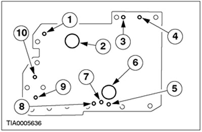
| Pos. | Spare Part No | Name |
| 1 | — | Releasing the servo block |
| 2 | — | Engaging the servo block |
| 3 | — | Engaging the direct drive clutch |
| 4 | — | Engaging the reverse clutch |
| 5 | — | Torque converter bypass |
| 6 | — | Low gear/Reverse gear coupling |
| 7 | — | Feed to the torque converter |
| 8 | — | Engaging the forward clutch |
| 9 | — | Engaging the servo block accumulator |
| 10 | — | Activating the forward servo unit accumulator. |
A no-shift condition can exist even with the correct transaxle fluid pressure due to faulty clutches and band brakes. Erratic shifting can be found by running a series of tests with air pressure instead of fluid pressure to locate the fault.
To locate a faulty clutch or band brake by applying air pressure to various test panel ports, follow the prescribed procedure.
NOTE: Use only dry, stabilized air with a maximum pressure of 3 bar.
Apply air to the appropriate port(s). When the element is engaged, there should be a dull, muffled sound or some movement may be felt. When the element is fully engaged, there should be no whistling sound.
1. Drain the transaxle fluid and remove the transmission fluid pan. For more information, refer to the Transaxle Fluid Pan, Gasket, and Filter section in this section.
2. Remove the main control valve block. For more information, refer to Main Control Valve Block in this section.
3. Install the transmission test panel and gasket. Use the transmission oil pan bolts to secure the test panel. Tighten the bolts to 10 Nm.
4. Apply air to the appropriate coupling port) (refer to the figure). If there are leaks in the coupling seals or ball check valves, a hissing sound may be heard. If the coupling seals or ball valves are leaking, a whistling sound may be heard.
If the test results show that the servo units are not working, disassemble them, clean and inspect them to find the source of the problem.
If air pressure supplied to the clutch passages fails to engage a clutch or another clutch engages at the same time, disassemble the assembly and use air pressure to check the passages in the center support and clutches to find any blockages.