Special tool
| Automotive tester 73III 105-R0057 or equivalent | |
| World Diagnostic System (WDS) 418 - F224 or equivalent scan tool | |
| Manometer assembly 307-004 (T57L-77820-A) | |
| Splitter box for 104-pin module EEC-V 014-00950 or equivalent |
Each time a plug connector is disconnected or a solenoid valve block is disconnected, inspect the plug connector for the condition of the contacts, corrosion and contamination. The sealing of the plug connector must also be inspected for damage. Clean, repair or install new ones if necessary.
Shift Solenoid Preliminary Diagnosis
When performing Pinpoint Test A, use the Shift Solenoid Valve Chart. For more information, please refer to the Specification available in this section.
Solenoid Valve Operation Chart - Torque Converter Engaged
| The main position of the gear selector | Transmission controlled by PCM | Switchover solenoid valve A (on off.) | Changeover solenoid valve B (on off.) | Switchover solenoid valve C (PWM) | Switchover solenoid valve D (PWM) | Switchover solenoid valve E (PWM) |
| P, N | P, N | Included | Turned off | Turned off | Turned off | Turned off |
| R | R | Turned off | Turned off | Turned off | Turned off | Turned off |
| D | 1 | Turned off | Turned off | Turned off | Included | Included |
| 1 (M) | Included | Included | Turned off | Turned off | Included | |
| 2 | Turned off | Turned off | Turned off | Turned off | Included | |
| 3 | Turned off | Turned off | Turned off | Turned off | Turned off | |
| 4 | Included | Turned off | Included | Turned off | Turned off |
With solenoid valve on/off, OFF (off) = No hydraulic flow with solenoid valve PWM, OFF (off) = Full hydraulic flow
Solenoid Valve Operation Chart - Torque Converter Engaged
| The main position of the gear selector | D gear controlled by PCM | Switchover solenoid valve A (on off.) | Changeover solenoid valve B (on off.) | Switchover solenoid valve C (PWM) | Switchover solenoid valve D (PWM) | Switchover solenoid valve E (PWM) |
| D | 3 | Turned off | Included | Included | Turned off | Turned off |
| 4 | Included | Included | Included | Turned off | Turned off |
With on/off solenoid valve, OFF = No hydraulic flow.
With PWM solenoid valve, OFF = Full hydraulic flow
PINPOINT TEST A: SOLENOID SHIFT VALVES AND TORQUE CONVERTER CLUTCH (ONLY)
|
STATES |
DETAILS/RESULTS/ACTIONS |
|
NOTE: Refer to the illustration of the transaxle harness connector prior to these Pinpoint tests. |
|
|
NOTE: Refer to the Transaxle Internal Harness Wiring Diagram prior to these Pinpoint tests. |
|
|
NOTE:Retrieve and record all DTCs. Before entering the output state control (OSC) all necessary actions should be worked out for all TR and OSS DTCs. |
|
|
A1: ELECTRONIC DIAGNOSIS SETUP |
|
|
1 Enter the OFF position. |
|
|
2 Gear selector in P. |
|
|
3 Before proceeding, make sure that the transaxle harness connector is properly installed, in good condition, and that the pins in the connector are properly engaged. |
|
|
4 Connect diagnostic tool.Scan tool |
|
|
5 Drive the ON position. |
|
|
6 Enter the following diagnostic tool diagnostic mode: Diagnostic Data Link. |
|
|
7 Enter the following diagnostic tool diagnostic mode: PCM. |
|
|
8 Enter the following diagnostic tool diagnostic mode: Active control modes. |
|
|
9 Enter the following diagnostic tool diagnostic mode: Output state control (OSC). |
|
|
10 Enter the following diagnostic tool diagnostic mode: Trans - Bench Mode (Bench mode for gearbox). |
|
|
• Is the vehicle entering Bench Mode? |
|
|
→ Yes |
|
|
STAY in Stand Mode. Go to A2 |
|
|
→ No |
|
|
REPEAT the procedure to enter Stand Mode. If the vehicle does not enter Standby Mode, REFER to PCED for information on PCM diagnostics. |
|
|
A2: WIGGLE TEST (WAVING CHECK OF WIRES/CONNECTORS) |
|
|
1 Remain in Stand Mode. |
|
|
2 Select the PID parameters to be controlled. - SSA - SSB - SSC - SSD - SSE |
|
|
3 Select "ON", to turn on the suspect solenoid valve. |
|
|
4 Click "SEND". |
|
|
5 Move/shake all transmission wiring and connectors in the transaxle assembly. Monitor for changes in solenoid valve status. |
|
|
6 Select "OFF", to turn off the solenoid valve. |
|
|
7 Click "SEND". |
|
|
• Is the fault status of the suspected solenoid valve changing? |
|
|
→ Yes |
|
|
REPAIR the electrical circuit. CHECK the system is working properly. |
|
|
→ No |
|
|
Go to A3 |
|
|
A3: CHECKING SOLENOID VALVE FUNCTION |
|
|
1 TURN ON/OFF each solenoid valve. |
|
|
• Does the solenoid valve turn on and off when commanded and can you hear its activation? |
|
|
→ Yes |
|
|
Go to A4 |
|
|
→ No |
|
|
Go to A5 |
|
|
A4: OSC TRANS - DRIVE MODE CHECK (DRIVING MODE FOR GEARBOX) |
|
|
1 Practice OSC Trans - Drive.. |
|
|
2 Select GEAR mode (BROADCAST) for shift solenoid valves or follow procedures for GEAR mode (BROADCAST), as specified in this section. |
|
|
3 Select TCC for torque converter clutch. Follow the TCC procedures in Drive mode as outlined in this section. |
|
|
• Does the transmission upshift and downshift or engage/disengage the torque converter when commanded? |
|
|
→ Yes |
|
|
CLEAR all DTCs. Carry out a road test to see if the problem is still present. If the problem is still present. For more information, refer to Symptom Diagnosis available in this section. to diagnose shifting or torque converter related problems. |
|
|
→ No |
|
|
Go to A5 |
|
|
A5: BATTERY VOLTAGE CHECK |
|
|
1 Disconnect the transaxle harness connector. |
|
|
2 Visually inspect all wires and plug connectors for damage. |
|

|
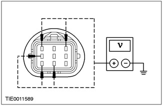
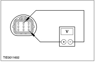
3 Measure the voltage between the following transaxle wiring harness connector pin, wiring side, and ground: - SSA - pin 6 - SSB - pin 8 - SSC - pin 3 - SSD - pin 9 - SSE - pin 1 |
|
• Is voltage being registered? |
|
|
→ Yes |
|
|
Go to A7 |
|
|
→ No |
|
|
Go to A6 |
|
|
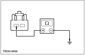
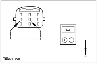
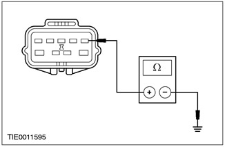
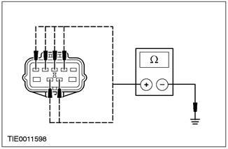
A6: CHECK FOR SHORT CIRCUIT TO " GROUND " |
|
|
1 Enter the OFF position. |
|

|
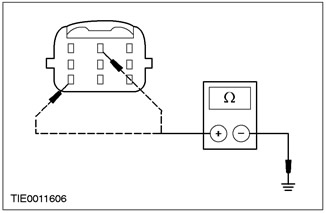
2 Measure the resistance between the following transaxle wiring harness connector pin, wiring side, and ground: - SSA - pin 6 - SSB - pin 8 - SSC - pin 3 - SSD - pin 9 - SSE - pin 1 |
|
• Is the resistance greater than 10,000 ohms? |
|
|
→ Yes |
|
|
Go to A8 |
|
|
→ No |
|
|
REPAIR the relevant electrical circuit. CHECK the system is working properly. |
|
|
A7: CHECK FOR SHORT CIRCUIT TO (+) BATTERY |
|
|
1 Disconnect the PCM male connector. |
|
|
2 Drive the ON position. |
|
|
3 Measure the voltage between the transaxle wiring harness connector pin below, wiring side, and ground: - SSA - pin 6 - SSB - pin 8 - SSC - pin 3 - SSD - pin 9 - SSE - pin 1 |
|
• Is there any voltage present? |
|
|
→ Yes |
|
|
REPAIR the relevant electrical circuit. CHECK the system is working properly. |
|
|
→ No |
|
|
INSTALL a new PCM. CHECK the system is working properly. |
|
|
A8: INSPECTION FOR OPEN CIRCUIT |
|
|
1 Disconnect the Powertrain Control Module. |
|
|
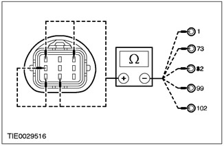
2 Install the splitter box for the 104-pin EEC - V module. |
|
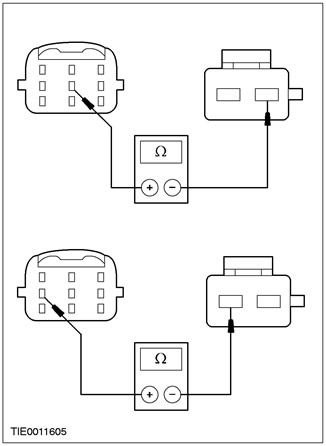
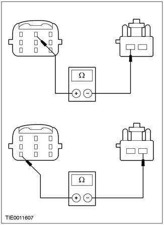
3 Measure the resistance between the following pins of the PCM connector, wiring side, and the following pins of the transaxle harness connector, wiring side, for the suspected solenoid valve: - SSA - pin 73 of the splitter box for the 104-pin EEC module - V - pin 6 of the gearbox connector in the block with the drive axle - SSB - pin 1 of the splitter box for the 104-pin EEC module - V - pin 8 of the gearbox connector in the block with the drive axle - SSC - pin 82 splitter boxes for 104-pin EEC module - V - pin 3 gearbox connectors in block with drive axle - SSD - pin 99 of the splitter box for the 104-pin EEC module - V- pin 9 of the gearbox connector in the block with the drive axle - SSE - pin 102 of the splitter box for the 104-pin EEC module - V - pin 1 of the gearbox connector in the block with the drive axle |
|
|
• Is the resistance less than 5 ohms? |
|
|
→ Yes |
|
|
Go to A9 |
|
|
→ No |
|
|
REPAIR the relevant electrical circuit. CHECK the system is working properly. |
|
|
A9: ELECTRICAL SIGNAL TEST |
|
|
1 Connect the PCM male connector. |
|
|
2 Drive the ON position. |
|
|
3 Measure the voltage between the transaxle harness connector pin below, wiring side, and ground for the suspect solenoid valve: - SSA - pin 6 - SSB - pin 8 - SSC - pin 3 - SSD - pin 9 - SSE - pin 1 |
|
|
4 Enter the following diagnostic tool diagnostic mode: Trans - Bench Mode (Bench mode for gearbox). |
|
|
5 Select SSA, SSB, SSC, SSD or SSE. |
|
|
6 Select "ON". |
|
|
7 Click "SEND". |
|
|
8 Measure the voltage when turning on/off the solenoid valve. |
|

|
9 Select "OFF", click "SEND". |
|
• Is the voltage changing? |
|
|
→ Yes |
|
|
Go to A10 |
|
|
→ No |
|
|
INSTALL a new PCM. CHECK the system is working properly. |
|
|
A10: SOLENOID VALVE ELECTRICAL RESISTANCE CHECK |
|
|
1 Measure the resistance between the following solenoid valve pin and the solenoid valve body, element side, for the suspected solenoid valve: - SSA - pin 6 and case - 10.9 - 26.2 ohm - SSB - pin 8 and case - 10.9 - 26.2 ohm - SSC - pin 3 and body - 1.0 - 4.2 ohm - SSD - pin 9 and case - 1.0 - 4.2 ohm - SSE - pin 1 and body - 1.0 - 4.2 ohm |
|
|
• Is the resistance correct? |
|
|
→ Yes |
|
|
If SSA or SSB is suspected, Go to A12. |
|
|
If SSC, SSD or SSE is suspected, Go to A11 |
|
|
→ No |
|
|
INSTALL a new SSA, SSB, SSC, SSD or SSE. CHECK the system is working properly. |
|
|
A11: CHECK SSC, SSD, SSE FOR SHORT CIRCUIT TO « GROUND » |
|
|
1 Measure the resistance between the suspect solenoid valve pin 1, element side, and the solenoid valve body. |
|
|
• Is the resistance less than 5 ohms? |
|
|
→ Yes |
|
|
INSTALL a new SSC, SSD or SSE. CHECK the system is working properly. |
|
|
→ No |
|
|
Go to A12 |
|
|
A12: INTERNAL DRIVE AXLE GEARBOX HARNESS CHECK FOR OPEN CIRCUIT |
|
|
1 Measure the resistance between the transaxle internal wiring harness connector pins below and the suspect solenoid valve connector pins: - SSA - between pin 6 of the transaxle internal wiring harness connector and pin 6 of the transaxle internal wiring harness solenoid valve connector - SSB - between pin 8 of the connector of the internal transmission wiring harness in the block with the driving axle and pin 8 of the solenoid valve connector of the internal wiring harness of the transmission in the block with the driving axle |
|
• Is the resistance less than 5 ohms? |
|
|
→ Yes |
|
|
Go to A13 |
|
|
→ No |
|
|
INSTALL a new internal transmission harness in the drive axle assembly. CHECK the system is working properly. |
|
|
A13: INTERNAL DRIVE AXLE GEARBOX HARNESS CHECK FOR OPEN CIRCUIT |
|
|
1 Measure the resistance between the transaxle internal wiring harness connector pins and the suspect solenoid valve connector pins: - SSC - between pin 3 of the transaxle internal wiring harness connector and pin 3 of the transaxle internal wiring harness solenoid valve connector - SSD - between pin 9 of the transaxle internal wiring harness connector and pin 9 of the transaxle internal wiring harness solenoid valve connector - SSE - between pin 1 of the transaxle internal wiring harness connector and pin 1 of the transaxle internal wiring harness solenoid valve connector |
|
• Is the resistance less than 5 ohms? |
|
|
→ Yes |
|
|
Go to A14 |
|
|
→ No |
|
|
INSTALL a new internal transmission harness in the drive axle assembly. CHECK the system is working properly. |
|
|
A14: INTERNAL DRIVE AXLE HARNESS GROUND CIRCUIT CHECK |
|
|
1 Measure the resistance between the following pins of the transaxle internal wiring harness connector to ground (lifting eye): - SSC - between pin 11 of the solenoid valve connector of the internal wiring harness of the gearbox in the block with the driving axle and "ground" (lifting eye) - SSD - between pin 12 of the solenoid valve connector of the internal wiring harness of the gearbox in the block with the drive axle and "ground" (lifting eye) - SSE - between pin 10 of the solenoid valve connector of the internal wiring harness of the gearbox in the block with the driving axle and "ground" (lifting eye) |
|
• Is the resistance less than 5 ohms? |
|
|
→ Yes |
|
|
INSTALL a new PCM. CHECK the system is working properly. |
|
|
→ No |
|
|
INSTALL a new internal transmission harness in the drive axle assembly. CHECK the system is working properly. |
|
PINPOINT TEST B: TRANSMISSION FLUID TEMPERATURE SENSOR (TFT)
|
STATES |
DETAILS/RESULTS/ACTIONS |
|
NOTE: Refer to the illustration of the transaxle harness connector prior to these Pinpoint tests. |
|
|
NOTE: Refer to the Transaxle Internal Harness Wiring Diagram prior to these Pinpoint tests. |
|
|
B1: ELECTRONIC DIAGNOSIS SETUP |
|
|
1 Enter the OFF position. |
|
|
2 Gear selector in P. |
|
|
3 Before proceeding, make sure that the transaxle harness connector is properly installed, in good condition, and that the pins in the connector are properly engaged. |
|
|
4 Connect diagnostic tool.Scan tool |
|
|
5 Drive the ON position. |
|
|
6 Select the diagnostic data link. |
|
|
7 Select PCM. |
|
|
8 Select the option PID/data monitoring and logging (PID/Data Monitor and Record). |
|
|
9 Enter the following diagnostic tool diagnostic mode: PID parameters; TFT, TFTV. |
|
|
• Vehicle enters PID/data monitoring and recording? |
|
|
→ Yes |
|
|
STAY in PID/Data Monitor and Record. Navigate to B2 |
|
|
→ No |
|
|
REPEAT the procedure to enter the PID. If the vehicle does not enter the PID, REFER to PCED for information on PCM diagnostics. |
|
|
B2: CYCLE CHECK WARM - UP/ COLD - DOWN |
|
|
1 When monitoring the PID TFT parameters, perform the following check: If the transaxle is cold, let it run to warm it up. If the transaxle is warm, allow the transaxle to cool down. |
|
|
• Does the TFT PID increase as the transaxle warms up, or decrease as the transaxle cools down or does the TFT or TFTV move in and out of operating range? |
|
|
→ Yes |
|
|
If the PID TFT parameters increase as the transaxle warms up or decreases as the transaxle cools down, CLEAR all DTCs. Carry out a road test to see if the problem is still present. If the problem is still present. For more information, refer to Symptom Diagnosis available in this section. to diagnose transaxle overheating. If the TFT goes into and out of operating range, INSPECT for an intermittent problem in the internal/external wiring harness, sensor, or plug connector. |
|
|
→ No |
|
|
Go to B3 |
|
|
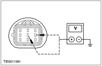
B3: CHECKING THE POWERTRAIN CONTROL MODULE AND VEHICLE WIRING HARNESS FOR POWER |
|
|
1 Disconnect the transaxle harness connector. |
|
|
2 Visually inspect all wires and plug connectors for damage. |
|

|
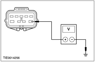
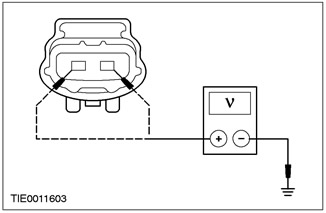
3 Measure the voltage between pin 5 of the transaxle wiring harness connector, wiring side, and ground; and between pin 4 of the transmission wiring harness connector in the drive axle assembly, on the wiring side, and ground. |
|
• Is there any voltage present? |
|
|
→ Yes |
|
|
Go to B4 |
|
|
→ No |
|
|
Go to B5 |
|
|
B4: CHECK THE VEHICLE WIRING HARNESS FOR A SHORT TO (+) BATTERY |
|
|
1 Disconnect the PCM male connector. |
|
|
2 Measure the voltage between pin 5 of the transaxle wiring harness connector, wiring side, and ground; and between pin 4 of the transmission wiring harness connector in the drive axle assembly, on the wiring side, and ground. |
|
• Is there any voltage present? |
|
|
→ Yes |
|
|
Repair the electrical circuit. Check the correct operation of the system. |
|
|
→ No |
|
|
INSTALL a new PCM. CHECK the system is working properly. |
|
|
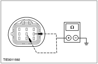
B5: CHECK POWERTRAIN CONTROL MODULE AND VEHICLE WIRING HARNESS FOR SHORT TO « GROUND » |
|
|
1 Connect the PCM male connector. |
|
|
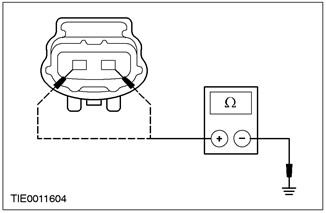
2 Measure the resistance between transaxle harness connector pin 5, wiring side, and ground; and between pin 4 of the transmission wiring harness connector in the drive axle assembly, on the wiring side, and ground. |
|
• Is the resistance greater than 10,000 ohms? |
|
|
→ Yes |
|
|
Go to B7 |
|
|
→ No |
|
|
Go to B6 |
|
|
B6: CHECK THE VEHICLE WIRING HARNESS FOR A SHORT TO « GROUND » |
|
|
1 Disconnect the PCM male connector. |
|

|
2 Measure the resistance between transaxle harness connector pin 5, wiring side, and ground; and between pin 4 of the transmission wiring harness connector in the drive axle assembly, on the wiring side, and ground. |
|
• Is the resistance greater than 10,000 ohms? |
|
|
→ Yes |
|
|
INSTALL a new PCM. CHECK the system is working properly. |
|
|
→ No |
|
|
REPAIR the electrical circuit. CHECK the system is working properly. |
|
|
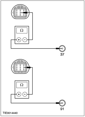
B7: CHECK VEHICLE WIRING HARNESS FOR OPEN CIRCUIT |
|
|
1 Install splitter box |
|
|
2 Measure the resistance between pin 5 of the transaxle cable harness connector, on the harness side, and pin 37 of the splitter box for the 104-pin EEC - V module, on the harness side; and between pin 4 of the transaxle wiring harness connector, on the wiring side, and pin 91 of the splitter box for the 104-pin EEC-V module, on the wiring side. |
|
• Is the resistance less than 5 ohms? |
|
|
→ Yes |
|
|
Go to B10 |
|
|
→ No |
|
|
Repair the electrical circuit. Check the correct operation of the system. |
|
|
B8: INTERNAL DRIVE AXLE GEARBOX HARNESS CHECK FOR SHORT TO " GROUND " |
|
|
1 Measure the resistance between pin 5 of the transaxle harness connector (element side, internal wiring harness for transaxle assembly) and "mass"; and between pin 4 of the transaxle wiring harness connector (element side, internal wiring harness for transaxle assembly) and "mass". |
|
• Is the resistance greater than 10,000 ohms? |
|
|
→ Yes |
|
|
Go to B9 |
|
|
→ No |
|
|
INSTALL a new internal transmission harness in the drive axle assembly. Check the correct operation of the system. |
|
|
B9: INTERNAL DRIVE AXLE GEARBOX HARNESS CHECK FOR OPEN CIRCUIT |
|
|
1 Measure the resistance between pin 5 of the transaxle harness connector (element side, internal wiring harness for transaxle assembly), and pin 5 connector of the internal wiring harness of the transmission fluid temperature sensor; and between pin 4 of the transaxle wiring harness connector (element side, internal wiring harness for transaxle assembly) and pin 4 of the internal transmission fluid temperature sensor harness connector. |
|
• Is the resistance less than 5 ohms? |
|
|
→ Yes |
|
|
Go to B10 |
|
|
→ No |
|
|
INSTALL a new internal transmission harness in the drive axle assembly. Check the correct operation of the system. |
|
|
B10: TFT SENSOR ELECTRICAL RESISTANCE CHECK |
|
|
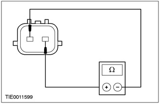
1 Measure the resistance between pin 5 of the transaxle harness connector (element side, internal wiring harness for transaxle assembly), and pin 4 of the transmission wiring harness connector in the block with the drive axle (element side, internal wiring harness for transaxle assembly). |
|
|
2 Record the result. |
|
|
3 The resistance should be approximately in the following ranges: - -20 ° C (-4 ° F) - 236 kΩ - 317 kΩ - 0 ° C (32 ° F) - 83.2 kOhm - 107 kOhm - 20 ° C (68 ° F) - 33.5 kΩ - 41.2 kΩ - 40 ° C (104 ° F) - 14.6 kΩ - 17.6 kΩ - 60 ° C (140 ° F) - 7.08 kOhm - 8.01 kOhm - 80 ° C (176 ° F) - 3.61 kOhm - 4.06 kOhm - 100 ° C (212 ° F) - 1.96 kOhm - 2.20 kOhm - 120 ° C (248 ° F) - 1.13 kΩ - 1.25 kΩ - 130 ° C (266 ° F) - 0.87 kΩ - 0.96 kΩ |
|
|
• Is the resistance within range? |
|
|
→ Yes |
|
|
For more information, refer to Symptom Diagnosis available in this section. to diagnose an overheating problem. |
|
|
→ No |
|
|
INSTALL a new TFT sensor. Check the correct operation of the system. |
|
PINPOINT TEST C: TRANSMISSION RANGE SENSOR (TR)
|
STATES |
DETAILS/RESULTS/ACTIONS |
|
NOTE: Refer to illustration of transmission range sensor connector (TR), that precedes these Pinpoint tests. |
|
|
NOTE: Refer to Transmission Range Sensor Diagnostic Chart (TR), that precedes these Pinpoint tests. |
|
|
NOTE: DTC P0705 can also be generated when the rear light circuit is open. Check and, if necessary, repair the rear light circuit. |
|
|
C1: TR POSITION ALIGNMENT CHECK |
|
|
1 Check TR sensor alignment. |
|
|
• Is the TR sensor correctly calibrated? |
|
|
→ Yes |
|
|
Go to C2 |
|
|
→ No |
|
|
ADJUST TR sensor. Check the correct operation of the system. |
|
|
C2: CHECK CABLE/SHIFT LINKAGE ADJUSTMENT |
|
|
1 Check shift cable/linkage for proper adjustment; REFER to Section 307 - 05. |
|
|
• Is the shift cable/lever adjusted correctly? |
|
|
→ Yes |
|
|
Go to C3 |
|
|
→ No |
|
|
ADJUST cable/shift linkage; REFER to Section 307 - 05. Check system for proper operation. |
|
|
C3: CHECK TR SENSOR POWER CIRCUIT AT START-UP |
|
|
1 Disconnect the TR sensor plug connector. |
|
|
2 Disconnect the C641 ignition coils. |
|
|
3 Drive the START position. |
|
|
4 Measure the voltage between pin 6 TR of the sensor connector, wiring side, and ground. |
|
• Is the voltage approximately 12 V? |
|
|
→ Yes |
|
|
Go to C4 |
|
|
→ No |
|
|
REPAIR starting circuit 50 - BB14 (gray-red). Check the correct operation of the system. |
|
|
C4: CHECKING THE ELECTRICAL POWER CIRCUIT OF THE DRIVE AXLE TRANSMISSION |
|
|
1 Connect the C641 ignition coil. |
|
|
2 Drive the ON position. |
|
|
3 Measure the voltage between pin 1 of the TR sensor connector, wiring side, and ground. |
|
• Is the voltage over 10V? |
|
|
→ Yes |
|
|
Go to C6 |
|
|
→ No |
|
|
Go to C5 |
|
|
C5: CHECK VEHICLE WIRING HARNESS FOR SHORT TO « GROUND » |
|
|
1 Enter the OFF position. |
|
|
2 Disconnect the PCM male connector. |
|
|
3 Measure the resistance between TR sensor connector pin 1, wiring side, and ground. |
|
• Is the resistance greater than 10,000 ohms? |
|
|
→ Yes |
|
|
Go to C6 |
|
|
→ No |
|
|
REPAIR the electrical circuit. CHECK the system is working properly. |
|
|
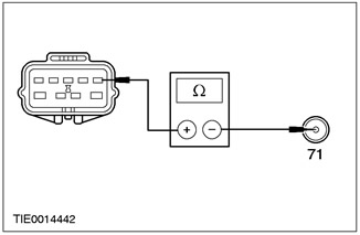
C6: CHECK VEHICLE HARNESS FOR OPEN CIRCUIT |
|
|
1 Enter the OFF position. |
|
|
2 Disconnect the PCM male connector. |
|
|
3 Install the splitter box for the 104-pin EEC - V module. |
|
|
4 Measure the resistance between pin 1 of the TR sensor, on the wiring side, and pin 71 of the splitter box for the 104-pin EEC - V module, on the wiring side. |
|
• Is the resistance less than 5 ohms? |
|
|
→ Yes |
|
|
Go to C7 |
|
|
→ No |
|
|
REPAIR the electrical circuit. CHECK the system is working properly. |
|
|
C7: CHECK THE TR SENSOR CIRCUIT FOR A SHORT TO (+) POWER |
|
|
1 Connect the PCM male connector. |
|
|
2 Select PARK. |
|
|
3 Drive the ON position. |
|

|
4 Measure the voltage between pins 2, 3, 4, 5, 7, and 8 of the TR sensor connector, harness side, and ground: |
|
• Is there any voltage present? |
|
|
→ Yes |
|
|
Go to C8 |
|
|
→ No |
|
|
Go to C10 |
|
|
C8: PCM CHECK FOR SHORT CIRCUIT TO (+) BATTERY |
|
|
1 Enter the OFF position. |
|
|
2 Disconnect the PCM male connector. |
|
|
3 Drive the ON position. |
|

|
4 Measure the voltage between pins 2, 3, 4, 5, 7, and 8 of the TR sensor connector, harness side, and ground: |
|
• Is there any voltage present? |
|
|
→ Yes |
|
|
REPAIR the relevant electrical circuit. CHECK the system is working properly. |
|
|
→ No |
|
|
INSTALL a new PCM. CHECK the system is working properly. |
|
|
C9: CHECK VEHICLE WIRING HARNESS FOR SHORT TO " GROUND " |
|
|
1 Enter the OFF position. |
|
|
2 Disconnect the PCM male connector. |
|
|
3 Disconnect Fuse 39 (10 A). |
|

|
4 Measure the resistance between pins 2, 3, 4, 5, 7, and 8 of the TR sensor connector, harness side, and ground: |
|
• Is the resistance greater than 10,000 ohms? |
|
|
→ Yes |
|
|
INSTALL a new PCM. CHECK the system is working properly. |
|
|
→ No |
|
|
REPAIR the relevant electrical circuit. CHECK the system is working properly. |
|
|
C10: CHECK TR SENSOR CIRCUIT FOR SHORT TO « GROUND » |
|
|
1 Enter the OFF position. |
|
|
2 Connect the PCM male connector. |
|
|
3 Disconnect Fuse 39 (10A). |
|
|
4 Measure the resistance between pins 2, 3, 4, 5, 7, and 8 of the TR sensor connector, harness side, and ground: |
|
• Is the resistance greater than 10,000 ohms? |
|
|
→ Yes |
|
|
Go to C11 |
|
|
→ No |
|
|
Go to C9 |
|
|
C11: TR SENSOR ELECTRICAL RESISTANCE TEST |
|
|
1 Connect Fuse 39 (10A). |
|
|
2 Measure the resistance between the following pins of the TR sensor connector, element side: - parking position P - pins 6 and 5, 8 and 9 of the sensor TR - less than 5 ohms - reverse gear R - sensor pins 1 and 4 TR - less than 5 ohms - neutral position N - sensor pins 1 and 8 TR - less than 5 ohms - motion transmission D - sensor pins 1 and 2 TR - less than 5 ohms - 2nd gear - TR sensor pins 1 and 7 - less than 5 ohms - 1 gear - TR sensor pins 1 and 3 - less than 5 ohms |
|
|
• Is the resistance within the expected range? |
|
|
→ Yes |
|
|
INSTALL a new PCM. CHECK the system is working properly. |
|
|
→ No |
|
|
INSTALL a new TR sensor. CHECK the system is working properly. |
|
PINPOINT TEST D: ELECTRONIC PRESSURE CONTROL SOLENOID VALVE (PCA)
|
STATES |
DETAILS/RESULTS/ACTIONS |
|
NOTE: Refer to the illustration of the transaxle harness connector prior to these Pinpoint tests. |
|
|
NOTE:Retrieve and record all DTCs. Before Entering Output State Control (OSC) take all necessary actions for all TR and OSS sensor DTCs. |
|
|
D1: ELECTRONIC DIAGNOSIS SETUP |
|
|
1 Enter the OFF position. |
|
|
2 Gear selector in position "P". |
|
|
3 Before proceeding, make sure that the transaxle harness connector is properly installed, in good condition, and that the pins in the connector are properly engaged. |
|
|
4 Install a 300 psi gauge in the line pressure test port. |
|
|
5 Connect diagnostic tool.Scan tool |
|
|
6 Drive the START position. |
|
|
7 Start the engine and let it run. |
|
|
8 Enter the following diagnostic tool diagnostic mode: Diagnostic Data Link. |
|
|
9 Enter the following diagnostic tool diagnostic mode: PCM. |
|
|
10 Enter the following diagnostic tool diagnostic mode: Active control modes. |
|
|
11 Enter the following diagnostic tool diagnostic mode: Output state control (OSC). |
|
|
12 Enter the following diagnostic tool diagnostic mode: Trans - Bench Mode (Bench mode for gearbox). |
|
|
• Is the vehicle entering Bench Mode? |
|
|
→ Yes |
|
|
STAY in Stand Mode. Go to D2 |
|
|
→ No |
|
|
REPEAT the procedure to ENTER Stand Mode. If the vehicle does not enter OSC, REFER to the Engine Management/Emission Control System Diagnostic Manual for PCM diagnostic information. |
|
|
D2: SOLENOID VALVE FUNCTIONAL CHECK |
|
|
1 Control pressure gauge. |
|
|
2 Enter the following diagnostic tool diagnostic mode: Parameter; PCA. |
|
|
3 Select PCA |
|
|
4 Increase engine speed to 1,500 rpm or more. |
|
|
5 Choose from 50, 70, 90, 110, 130, or 150 psi. |
|
|
6 Click "SEND". |
|
|
7 Choose another value "50-150 psi". |
|
|
8 Click "SEND". |
|
|
9 Enter the following diagnostic tool diagnostic mode: XXX. |
|
|
10 Click "SEND". |
|
|
• Does the pressure reading correspond to the required pressure? |
|
|
→ Yes |
|
|
Clear the DTCs. CHECK the system is working properly. |
|
|
→ No |
|
|
Go to D3 |
|
|
D3: CHECK VEHICLE WIRING HARNESS AND POWER PACK CONTROL MODULE FOR A SHORT TO (+) BATTERY |
|
|
1 Enter the OFF position. |
|
|
2 Disconnect the transaxle harness connector. |
|
|
3 Visually inspect all wires and plug connectors for damage. |
|
|
4 Drive the ON position. |
|
|
5 Measure the voltage between pin 7 of the transaxle wiring harness connector, wiring side, and ground; and between pin 2 of the transmission wiring harness connector in the drive axle assembly, on the wiring side, and ground. |
|
• Is there any voltage present? |
|
|
→ Yes |
|
|
Go to D4 |
|
|
→ No |
|
|
Go to D5 |
|
|
D4: CHECK VEHICLE WIRING HARNESS FOR SHORT TO « GROUND » |
|
|
1 Enter the OFF position. |
|
|
2 Disconnect the PCM male connector. |
|
|
3 Drive the ON position. |
|

|
4 Measure the voltage between pin 7 of the transaxle wiring harness connector, wiring side, and ground; and between pin 2 of the transmission wiring harness connector in the drive axle assembly, on the wiring side, and ground. |
|
• Is there any voltage present? |
|
|
→ Yes |
|
|
REPAIR the electrical circuit. CHECK the system is working properly. |
|
|
→ No |
|
|
INSTALL a new PCM. CHECK the system is working properly. |
|
|
D5: ELECTRICAL SIGNAL TEST |
|
|
1 Measure the voltage between pin 7 of the transaxle harness connector on the harness side and pin 2 of the transaxle harness connector on the harness side. |
|
|
2 Turn on/off the solenoid valves while monitoring the voltage reading. |
|
|
3 Enter the following diagnostic tool diagnostic mode: Trans - Bench Mode (Bench mode for gearbox). |
|
|
4 Enter the following diagnostic tool diagnostic mode: Parameter; PCA. |
|
|
5 Select value "50-150 psi". |
|
|
6 Click "SEND". |
|
|
7 Choose another value "50-150 psi". |
|
|
8 Click "SEND". |
|
|
9 Enter the following diagnostic tool diagnostic mode: XXX. |
|
|
10 Click SEND. |
|
• Is the voltage changing? |
|
|
→ Yes |
|
|
Go to D6 |
|
|
→ No |
|
|
INSPECT the wiring harness or PCM for an open or short in the electrical circuit. |
|
|
D6: INTERNAL DRIVE AXLE GEARBOX HARNESS CHECK FOR SHORT TO " GROUND " |
|
|
1 Enter the OFF position. |
|
|
2 Disconnect the PCA solenoid valve plug. |
|
|
3 Measure the resistance between pin 2 of the transaxle harness connector (element side, internal wiring harness for transaxle assembly), and "mass"; and between pin 7 of the transmission wiring harness connector in the block with the drive axle (element side, internal wiring harness for transaxle assembly), and "mass". |
|
• Is the resistance greater than 10,000 ohms? |
|
|
→ Yes |
|
|
Go to D7 |
|
|
→ No |
|
|
INSTALL a new internal transmission harness in the drive axle assembly. Check the correct operation of the system. |
|
|
D7: INTERNAL DRIVE AXLE GEARBOX HARNESS CHECK FOR OPEN CIRCUIT |
|
|
1 Measure the resistance between pin 2 of the transaxle harness connector (element side, internal wiring harness for transaxle assembly), and pin 2 of the connector of the internal wiring harness of the gearbox in the block with the drive axle; and between pin 7 of the transmission wiring harness connector in the block with the drive axle (element side, internal wiring harness for transaxle assembly), and pin 7 of the connector of the internal wiring harness of the gearbox in the block with the drive axle. |
|
• Is the resistance less than 5 ohms? |
|
|
→ Yes |
|
|
Go to D8 |
|
|
→ No |
|
|
INSTALL a new internal transmission harness in the drive axle assembly. Check the correct operation of the system. |
|
|
D8: SOLENOID VALVE COIL RESISTANCE TEST |
|
|
1 Enter the OFF position. |
|
|
2 Measure the resistance between the pins of the PCA solenoid valve and record the result. |
|
|
• Is the resistance between 2.4 and 7.3 ohms? |
|
|
→ Yes |
|
|
Go to D9 |
|
|
→ No |
|
|
INSTALL a new PCA solenoid valve. Check the correct operation of the system. |
|
|
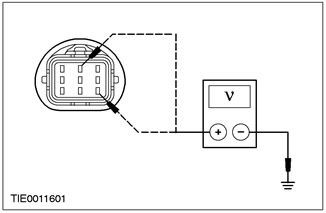
D9: CHECK SOLENOID VALVE CIRCUIT FOR SHORT TO " GROUND " |
|
|
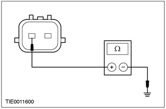
1 Measure the resistance between the PCA solenoid valve and the solenoid valve body and record the result. |
|
|
• Is the resistance greater than 10,000 ohms? |
|
|
→ Yes |
|
|
For more information, refer to Symptom Diagnosis available in this section. to diagnose pressure problems. CHECK the system is working properly. |
|
|
→ No |
|
|
INSTALL a new PCA solenoid valve. CHECK the system is working properly. |
|
PINPOINT TEST E: TURBINE SPEED SENSOR (TSS) AND OUTPUT SHAFT SPEED SENSOR (OSS)
|
STATES |
DETAILS/RESULTS/ACTIONS |
|
NOTE: Refer to Turbine Speed Sensor Connector Illustrations (TSS) and secondary shaft speed sensor (OSS), that precedes these Pinpoint tests. |
|
|
E1: ELECTRONIC DIAGNOSIS SETUP |
|
|
1 Before proceeding, check that the transaxle harness connector is properly installed, in good condition, and that the pins in the connector are properly seated. |
|
|
2 Connect diagnostic tool.Scan tool |
|
|
3 Drive the ON position. |
|
|
4 Enter the following diagnostic tool diagnostic mode: Diagnostic Data Link. |
|
|
5 Enter the following diagnostic tool diagnostic mode: PCM. |
|
|
6 Select Trans Priority Mode (transmission priority mode). |
|
|
7 Select PID/Data Monitor and Record option (PID/data monitoring and recording). |
|
|
8 Select the following PID parameters: TSS or OSS. |
|
|
• The vehicle enters the option PID/data monitoring and recording? |
|
|
→ Yes |
|
|
STAY in PID/Data Monitor and Record. Go to E2 |
|
|
→ No |
|
|
REPEAT the procedure to ENTER the PID. If the vehicle does not enter the PID, REFER to PCED for information on PCM diagnostics. |
|
|
E2: MOTION CYCLE CHECK |
|
|
1 While monitoring the PID of the corresponding sensor, drive the vehicle so that the transmission upshifts and downshifts through all gears. |
|
|
• Does the TSS or OSS speed PID increase and decrease according to changes in engine speed and vehicle speed? |
|
|
→ Yes |
|
|
Go to E3 |
|
|
→ No |
|
|
If the TSS or OSS speed PID does not increase or decrease in response to changes in engine speed and vehicle speed, INSPECT the vehicle wiring harness and sensor for an open or short in the electrical circuit, or for problems in the PCM or internal electronics problems. Go to E4 |
|
|
E3: SIGNAL RANDOM CHECK IN MOTION CYCLE |
|
|
1 By monitoring the PID of the corresponding sensor, drive the vehicle so that the transmission upshifts and downshifts through all gears. |
|
|
• TSS or OSS speed PID signal is erratic (drops to zero or close to zero and returns to normal)? |
|
|
→ Yes |
|
|
If the sensor signal is erratic, INSPECT the wiring harness, sensor, or plug connector for an intermittent problem. Go to E4 |
|
|
→ No |
|
|
CLEAR all DTCs. Practice OBD procedures. |
|
|
E4: CHECK POWER PACK CONTROL MODULE AND WIRING HARNESS FOR POWER |
|
|
1 Enter the OFF position. |
|
|
2 Disconnect the TSS sensor plug connector. |
|
|
3 Disconnect the OSS sensor plug connector. |
|
|
4 Drive the ON position. |
|
|
5 For TSS, measure the voltage between pin 1 of the TSS sensor connector, wiring side, and ground; and between pin 2 of the TSS sensor connector, wiring side and ground. |
|
|
6 For OSS, measure the voltage between pin 1 of the OSS connector, wiring side, and ground; and between pin 2 of the OSS connector, wiring side and ground. |
|
• Is there any voltage present? |
|
|
→ Yes |
|
|
Go to E5 |
|
|
→ No |
|
|
Go to E6 |
|
|
E5: CHECK THE WIRING HARNESS FOR A SHORT TO (+) BATTERY |
|
|
1 Enter the OFF position. |
|
|
2 Disconnect the PCM male connector. |
|
|
3 Drive the ON position. |
|
|
4 For TSS, measure the voltage between pin 1 of the TSS sensor connector, wiring side, and ground; and between pin 2 of the TSS sensor connector, wiring side and ground. |
|
|
5 For OSS, measure the voltage between pin 1 of the OSS connector, wiring side, and ground; and between pin 2 of the OSS connector, wiring side and ground. |
|
• Is there any voltage present? |
|
|
→ Yes |
|
|
REPAIR the relevant electrical circuit. CHECK the system is working properly. |
|
|
→ No |
|
|
INSTALL a new PCM. CHECK the system is working properly. |
|
|
E6: POWER PACK CONTROL MODULE AND WIRING HARNESS GROUND CHECK |
|
|
1 Enter the OFF position. |
|
|
2 Connect C415 PCM. |
|
|
3 For TSS, measure the resistance between TSS connector pin 1, wiring side, and ground; and between pin 2 of the TSS sensor connector, wiring side and ground. |
|

|
4 For OSS, measure the resistance between pin 1 of the OSS connector, wiring side, and ground; and between pin 2 of the OSS connector, wiring side and ground. |
|
• Is the resistance greater than 10,000 ohms? |
|
|
→ Yes |
|
|
Go to E8 |
|
|
→ No |
|
|
Go to E7 |
|
|
E7: CHECK THE WIRING HARNESS FOR A SHORT TO « GROUND » |
|
|
1 Enter the OFF position. |
|
|
2 Disconnect the PCM male connector. |
|
|
3 For TSS, measure the resistance between TSS connector pin 1, wiring side, and ground; and between pin 2 of the TSS sensor connector, wiring side, and ground. |
|
|
4 For OSS, measure the resistance between pin 1 of the OSS connector, wiring side, and ground; and between pin 2 of the OSS connector, wiring side and ground. |
|
• Is the resistance greater than 10,000 ohms? |
|
|
→ Yes |
|
|
INSTALL a new PCM. CHECK the system is working properly. |
|
|
→ No |
|
|
REPAIR the relevant electrical circuit. CHECK the system is working properly. |
|
|
E8: TSS OR OSS ELECTRICAL CIRCUIT RESISTANCE TEST. |
|
|
1 For TSS, measure the resistance between pin 1 of the TSS sensor connector, element side, and pin 2 of the TSS sensor connector, element side. |
|
|
2 For OSS, measure the resistance between pin 1 of the OSS connector, element side, and pin 2 of the OSS connector, element side. |
|
|
3 Record the results. The resistance should be as follows: - OSS 675 - 775 Ohm at -20°C (- 4 ° F) - OSS 800 - 920 Ohm at 21°C (70 ° F) - OSS 1210 - 1390 Ohm at 160°C (302 ° F) - TSS 273 - 333 Ohm at -20°C (- 4 ° F) - TSS 330 - 390 Ohm at 21°C (70 ° F) - TSS 487 - 601 Ohm at 160°C (302 ° F) |
|
• Is the resistance within specification for the appropriate sensor? |
|
|
→ Yes |
|
|
Go to E9 |
|
|
→ No |
|
|
INSTALL a new sensor. CHECK the system is working properly. |
|
|
E9: CHECKING SENSORS FOR A SHORT TO " GROUND " |
|
|
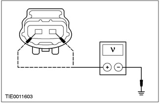
1 For TSS, measure the resistance between pin 1 of the TSS sensor connector, element side, and ground. |
|
|
2 For OSS, measure the resistance between pin 1 of the OSS connector, element side, and ground. |
|
• Is the resistance greater than 10,000 ohms? |
|
|
→ Yes |
|
|
INSTALL a new TSS or OSS sensor. Check the correct operation of the system. |
|
|
→ No |
|
|
For more information, refer to Symptom Diagnosis available in this section. to diagnose shift problems or torque converter problems. |
|
Visitor comments