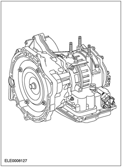
Description of the gearbox in a block with a driving axle
The automatic transmission used on this vehicle is a new development.
It is a fully automatic, electronically controlled, four speed transmission designed for use in front wheel drive vehicles.
The short designation of the gearbox is 4F27E, which stands for:
- 4 - 4-speed gearbox,
- F - front wheel drive,
- 27 - maximum input torque after torque converter: 365 Nm (270 lb-ft)
- E - fully electronic control.
The individual gear ratios are achieved using a two-stage planetary gear, the stages of which are arranged one behind the other.
The individual elements of the planetary stages are driven or held by three multi-disc clutches, multi-disc brakes, band brakes and a single-acting roller clutch.
Torque is transmitted to the main gear through an intermediate gear.
The fluid is changed in accordance with the Scheduled Maintenance Manual supplied with the vehicle. The electrical and hydraulic functions are controlled by the EEC V Powertrain Control Module with a 104-pin connector. The manual gear lever provides the driver with a choice between gears "P", "R", "N", "1", "2" And "D".
In range of motion "D" You can also use the O/D switch on the gear selector to prevent the transmission from shifting into 4th gear or shift the transmission from 4th to 3rd gear.
To reduce fuel consumption, the torque converter lock-up clutch in 3rd and 4th gears is locked by the PCM depending on the throttle position and vehicle speed.
The gearbox has an electronically controlled synchronized gearshift (ESSC), which guarantees smooth gear shifting throughout the life of the gearbox.
The hydraulic emergency operating program maintains limited transmission action in the event of failure of critical electrical components.
The gearbox can be checked with the FDS 2000 or WDS via the data link connector (DLC), located in the passenger compartment.
- 1st gear: 2.816:1
- 2nd gear: 1.498:1
- 3rd gear: 1.000:1
- 4th gear: 0.726:1
- Reverse gear ratio: 2.649:1
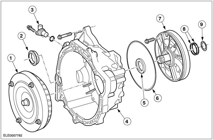
Torque converter housing with torque converter and hydraulic fluid pump
| Pos. | Spare Part No | Name |
| 1 | - | Torque converter assembly |
| 2 | - | Differential seal assembly |
| 3 | - | Secondary shaft speed sensor (OSS) |
| 4 | - | Torque converter housing |
| 5 | - | Fluid pump seal assembly |
| 6 | - | Fluid Pump Seal |
| 7 | - | Fluid pump assembly |
| 8 | - | Forward Clutch Cylinder Seal |
| 9 | - | Thrust washer of a support of the pump of a working liquid |
Forward clutch

| Pos. | Spare Part No | Name |
| 1 | - | Turbine shaft assembly |
| 2 | - | Forward clutch piston assembly |
| 3 | - | Forward Clutch Piston Return Spring Assy |
| 4 | - | Forward clutch balancing piston |
| 5 | - | Retaining ring for forward clutch balancing piston |
| 6 | - | Forward Clutch Separating Steel Disc (4 things.) |
| 7 | - | Forward clutch friction disc assembly (forward movement, 4 pcs.) |
| 8 | - | Forward/Direct Clutch Pressure Plate (1 pc. for each clutch) |
| 9 | - | Retaining ring (selective selection) |
| 10 | - | Forward clutch cylinder hub |
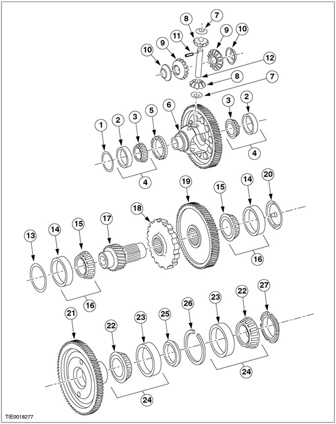
Differential assembly and final drive input - vehicles manufactured up to 06.2000
| Pos. | Spare Part No | Name |
| 1 | - | Adjusting gasket (shim) differential bearing |
| 2 | - | Differential outer ring |
| 3 | - | roller bearing inner ring |
| 4 | - | Bearing assembly |
| 5 | - | OSS sensor wheel |
| 6 | - | Differential and gear assembly of the gearbox in the block with the drive axle |
| 7 | - | Thrust washer of pinion differential (2 pcs.) |
| 8 | - | Differential satellite (2 pcs.) |
| 9 | - | Differential side gear (2 pcs.) |
| 10 | - | Thrust washer side gear (2 pcs.) |
| 11 | - | Pin |
| 12 | - | Axis of differential pinions |
| 13 | - | Adjusting gasket (shim) roller bearing of transmission shaft |
| 14 | - | Transmission shaft roller bearing outer race |
| 15 | - | roller bearing inner ring |
| 16 | - | Bearing assembly transmission shaft (2 pcs.) |
| 17 | - | Transmission shaft secondary gear |
| 18 | - | Park gear |
| 19 | - | Transmission shaft primary gear |
| 20 | - | Transfer shaft funnel |
| 21 | - | final drive gear |
| 22 | - | roller bearing inner ring |
| 23 | - | Bearing outer ring |
| 24 | - | Bearing assembly (2 pcs.) |
| 25 | - | remote element |
| 26 | - | Retaining ring |
| 27 | screw |
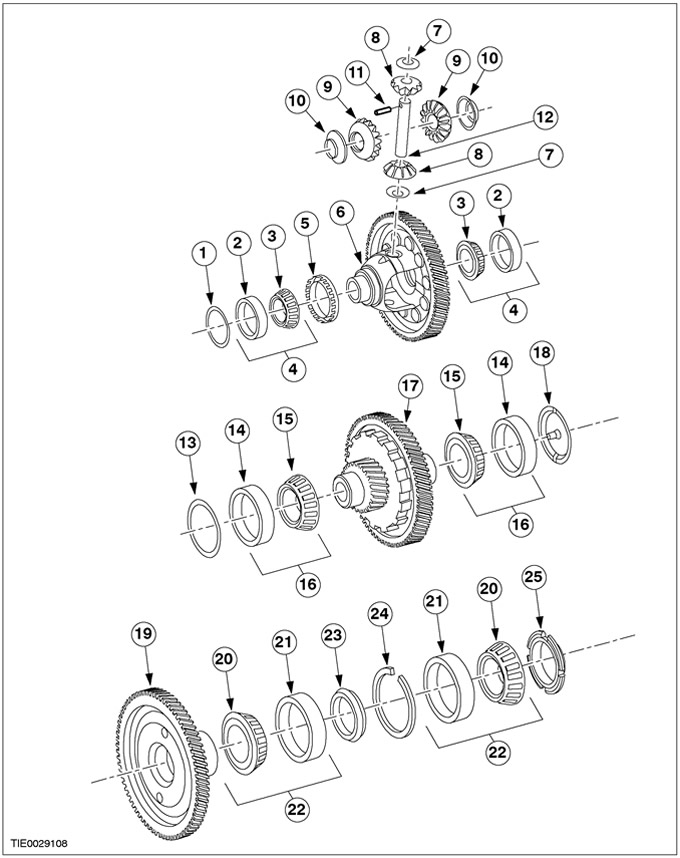
Differential assembly and final drive input - vehicles manufactured from 06.2000
| Pos. | Spare Part No | Name |
| 1 | - | Adjusting gasket (shim) differential bearing |
| 2 | - | Differential outer ring |
| 3 | - | roller bearing inner ring |
| 4 | - | Bearing assembly |
| 5 | - | OSS sensor wheel |
| 6 | - | Differential and gear assembly of the gearbox in the block with the drive axle |
| 7 | - | Thrust washer of pinion differential (2 pcs.) |
| 8 | - | Differential satellite (2 pcs.) |
| 9 | - | Differential side gear (2 pcs.) |
| 10 | - | Thrust washer side gear (2 pcs.) |
| 11 | - | Pin |
| 12 | - | Axis of differential pinions |
| 13 | - | Adjusting gasket (shim) roller bearing of transmission shaft |
| 14 | - | Transmission shaft roller bearing outer race |
| 15 | - | roller bearing inner ring |
| 16 | - | Bearing assembly transmission shaft (2 pcs.) |
| 17 | - | Gear wheel of a transfer shaft assy |
| 18 | - | Transfer shaft funnel |
| 19 | - | final drive gear |
| 20 | - | roller bearing inner ring |
| 21 | - | Bearing outer ring |
| 22 | - | Bearing assembly (2 pcs.) |
| 23 | - | remote element |
| 24 | - | Retaining ring |
| 25 | - | screw |
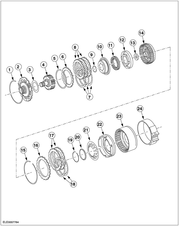
Couplings and planetary gear

| Pos. | Spare Part No | Name |
| 1 | - | Low/Reverse Clutch Piston |
| 2 | - | Low/Reverse Clutch Return Spring |
| 3 | - | Inner ring OWC low gear |
| 4 | - | Retaining ring OWC low gear |
| 5 | - | Low/Reverse Clutch Diaphragm Spring |
| 6 | - | Steel spacer ring for low/reverse clutch (5 pieces.) |
| 7 | - | Friction Disc Assembly Low/Reverse Clutch (5 pieces.) |
| 8 | - | Low/Reverse Clutch Pressure Plate |
| 9 | - | Low/Intermediate Clutch Disc Retaining Ring (selective selection) |
| 10 | - | Single-acting low gear clutch stopper |
| 11 | - | OWC Assy Low Gear Single Acting Clutch |
| 12 | - | Retaining ring |
| 13 | - | Front ring gear |
| 14 | - | Front planetary gear assembly |
| 15 | - | Thrust bearing assembly of the front planet carrier |
| 16 | - | Retaining ring |
| 17 | - | Front planetary sun gear assembly |
| 18 | - | Thrust bearing assembly sun gear front planetary gear |
| 19 | - | Rear planetary gear assembly |
| 20 | - | Retaining ring |
Clutches and band brake
| Pos. | Spare Part No | Name |
| 1 | - | Reverse Clutch Retaining Ring |
| 2 | - | Rear planetary sun gear assembly |
| 3 | - | Thrust bearing assembly for rear planetary sun gear |
| 4 | - | Direct drive clutch hub assembly |
| 5 | - | Retaining ring |
| 6 | - | Forward/Direct Clutch Pressure Plate (1 pc. for each) |
| 7 | - | Friction Disc Assy Forward/Direct Clutch (for the forward drive clutch - 4 pcs., for the direct drive clutch - 3 pcs.) |
| 8 | - | Steel Disc Direct Drive Clutch (3 pcs.) |
| 9 | - | Direct Clutch Balance Piston Retaining Ring |
| 10 | - | Direct Clutch Balance Piston |
| 11 | - | Forward/Direct Clutch Piston Return Spring Assembly |
| 12 | - | Direct clutch piston assembly |
| 13 | - | Direct Drive Clutch Thrust Bearing Assembly |
| 14 | - | Cylinder Assembly Direct Drive Clutch |
| 15 | - | Reverse Clutch Retaining Ring (selective selection) |
| 16 | - | Reverse clutch pressure plate |
| 17 | - | Steel Disc Reverse Clutch (2 pcs.) |
| 18 | - | Friction disc assembly reverse clutch (2 pcs.) |
| 19 | - | Reverse Clutch Retaining Ring |
| 20 | - | Reverse clutch lock |
| 21 | - | Reverse clutch piston return spring |
| 22 | - | Reverse clutch piston assembly |
| 23 | - | Drum assembly intermediate / overdrive |
| 24 | - | Intermediate/Overdrive Band Brake Assembly |
Main control box assembly
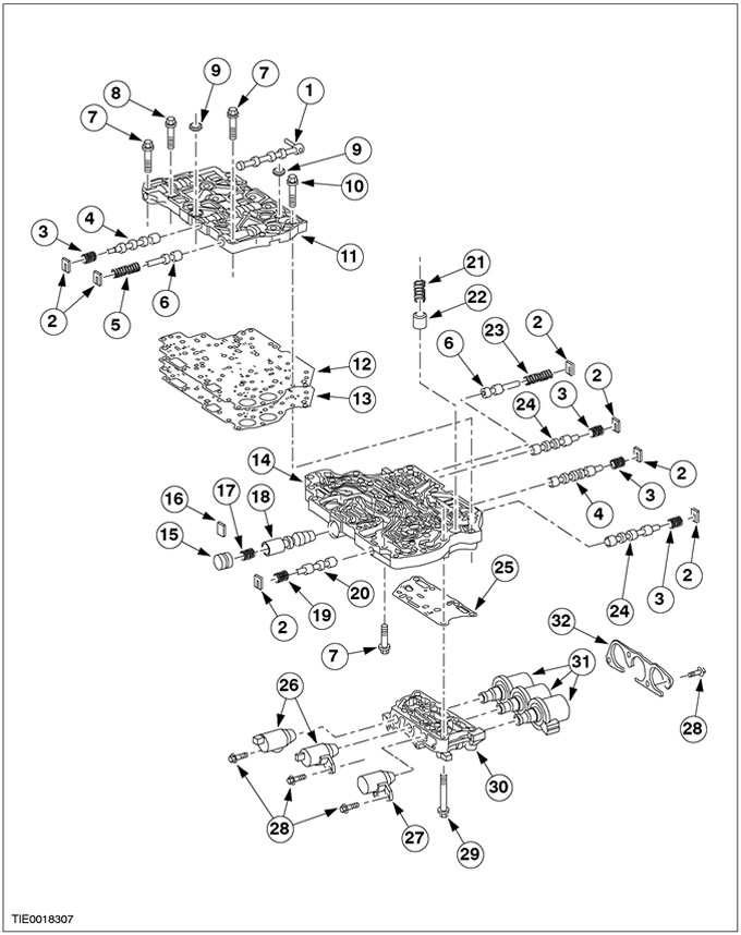
| Pos. | Spare Part No | Name |
| 1 | - | Manual valve assembly |
| 2 | - | Spring stop plate (7 pcs.) |
| 3 | - | Clutch Control Bypass Valve Control Spring (4 things.) |
| 4 | - | Clutch control bypass valve (2 pcs.) |
| 5 | - | Modulating valve spring) |
| 6 | - | Line pressure modulation valve (and releasing the torque converter) (2 pcs.) |
| 7 | - | Bolt М6х40 (3 pcs.) |
| 8 | - | Bolt М6х30 (5 pieces.) |
| 9 | - | Valve block seal |
| 10 | - | Bolt М6х60 (5 pieces.) |
| 11 | - | Upper control valve block |
| 12 | - | Gasket/disc assembly control valve block |
| 13 | - | Control valve block spacer |
| 14 | - | Lower control valve block |
| 15 | - | Main control valve stopper |
| 16 | - | Main control valve stop plate |
| 17 | - | Main line pressure control valve spring |
| 18 | - | Main line pressure control valve |
| 19 | - | Solenoid valve spring |
| 20 | - | Solenoid control valve |
| 21 | - | Intermediate servo accumulator spring |
| 22 | - | intermediate gear servo accumulator piston |
| 23 | - | Torque converter control valve spring |
| 24 | - | Blocking and switching control valve 3-4 (2 pcs.) |
| 25 | - | Solenoid valve block gasket |
| 26 | - | Shift control solenoid valve (2 pcs.) |
| 27 | - | Pressure Control Solenoid Valve Assembly |
| 28 | - | Screw M6x15 (7 pcs.) |
| 29 | - | Screw M6x72 (2 pcs.) |
| 30 | - | Block of electromagnetic throttle valves of switching |
| 31 | - | Shift control solenoid valve assembly (3 pcs.) |
| 32 | - | H/DWN Shift Control Solenoid Valve Bracket |
Carter assembly
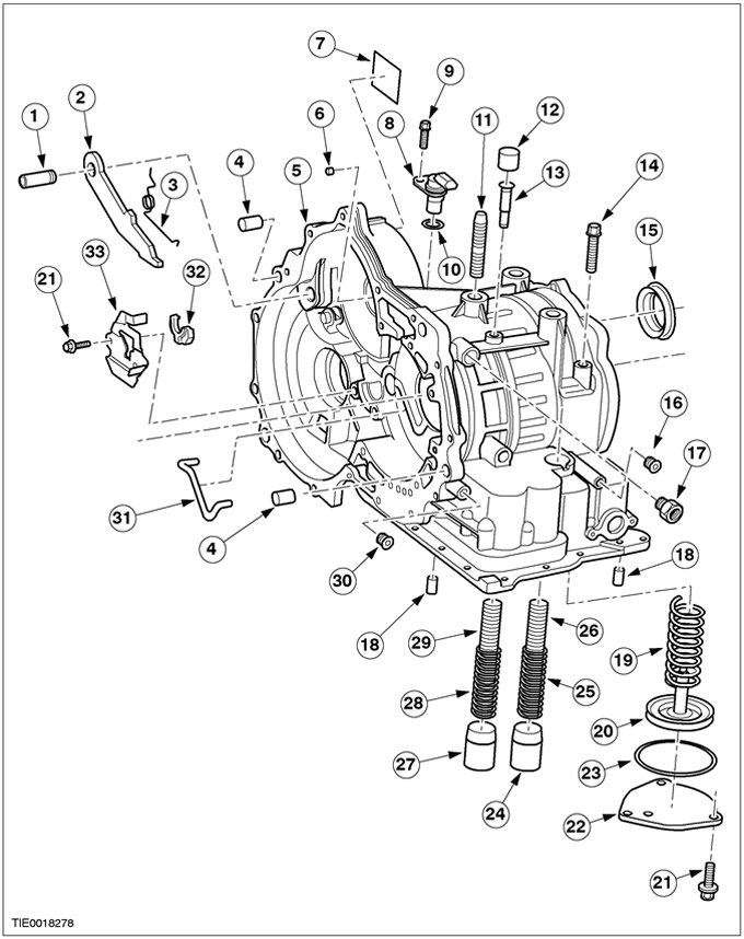
| Pos. | Spare Part No | Name |
| 1 | – | Axle of the parking latch |
| 2 | – | Parking brake pawl |
| 3 | – | Pawl return spring |
| 4 | – | Pin |
| 5 | – | Carter |
| 6 | – | Crankcase jet plug |
| 7 | – | Service identification plate |
| 8 | – | TSS sensor |
| 9 | – | Bolt M6-1 x 20 |
| 10 | – | O-ring of circular cross-section |
| 11 | – | crankcase stud |
| 12 | – | Rubber vent cap |
| 13 | – | breather tube |
| 14 | – | Overdrive Band Brake Anchor Stud |
| 15 | – | differential seal |
| 16 | – | Hex socket 1/8-27 |
| 17 | – | Connector? x 5/8 x 22.9 |
| 18 | – | Crankcase dowel pin |
| 19 | – | Servo Piston Return Spring |
| 20 | – | Servo Piston Assembly with Intermediate and Overdrive Seal |
| 21 | – | Screw M6-1 x 20 |
| 22 | – | Band brake servo cover for intermediate and overdrive gears |
| 23 | – | Cover seal for intermediate and overdrive servo unit |
| 24 | – | Neutral accumulator/driving drive piston |
| 25 | – | Outer Spring for Neutral/Drive Shift Accumulator |
| 26 | – | Neutral/driving shift accumulator internal spring |
| 27 | – | Switch accumulator piston 1-2 |
| 28 | – | Switch accumulator outer spring 1-2 |
| 29 | – | Switch accumulator inner spring 1-2 |
| 30 | – | Line pressure test plug |
| 31 | – | Oil transfer line |
| 32 | – | Park latch adjustment actuator |
| 33 | – | Park latch actuator plate |
Seals, O-rings and gaskets
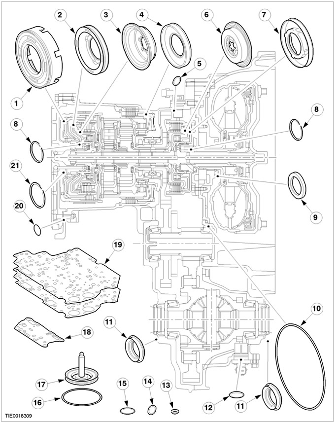
| Pos. | Spare Part No | Name |
| 1 | - | Reverse clutch piston assembly |
| 2 | - | Direct clutch piston assembly |
| 3 | - | Direct Clutch Balance Piston |
| 4 | - | Low/Reverse Clutch Piston |
| 5 | - | O-ring for turbine speed sensor |
| 6 | - | Direct Clutch Balance Piston |
| 7 | - | Direct clutch piston assembly |
| 8 | - | Forward and Direct Clutch Cylinder Seal (4 things.) |
| 9 | - | Seal assembly for hydraulic fluid pump |
| 10 | - | Fluid Pump Seal |
| 11 | - | Differential seal assy |
| 12 | - | O-ring for secondary shaft speed sensor |
| 13 | - | Valve block seal (2 pcs.) |
| 14 | - | Hand shaft seal (2 pcs.) |
| 15 | - | Fluid filter seal |
| 16 | - | Overdrive Servo Cover Seal |
| 17 | - | Piston and seal assembly for intermediate and overdrive servo unit |
| 18 | - | Solenoid valve block gasket |
| 19 | - | Control valve block gasket (2 pcs.) |
| 20 | - | Crankcase cover seal (2 pcs.) |
| 21 | - | Reverse Clutch Cylinder Seal (2 pcs.) |
Retaining rings
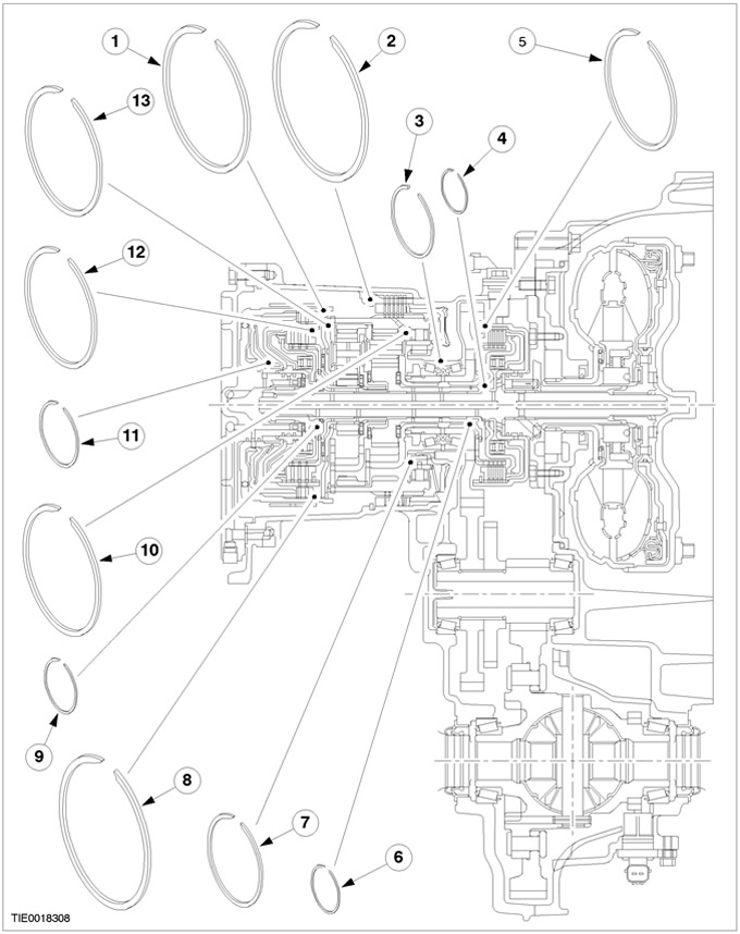
| Pos. | Spare Part No | Name |
| 1 | - | Reverse Clutch Retaining Ring |
| 2 | - | Low/Reverse Clutch Disc Retaining Ring (selective selection) |
| 3 | - | Final drive retaining ring |
| 4 | - | Forward clutch balancing piston ring |
| 5 | - | Forward/Direct Clutch Disc Retaining Ring (selective selection) |
| 6 | - | Front planetary sun gear retaining ring |
| 7 | - | Retaining ring OWC low gear |
| 8 | - | Reverse Clutch Retaining Ring (selective selection) |
| 9 | - | Retaining ring for DC balancing piston |
| 10 | - | Planetary Retaining Ring Forward/Direct Clutches |
| 11 | - | Reverse Clutch Spring Retaining Ring |
| 12 | - | Forward/Direct Clutch Disc Retaining Ring (selective selection) |
| 13 | - | Retaining ring of a back planetary gear assy |
Rolling and sliding bearings (bushings) and thrust washers
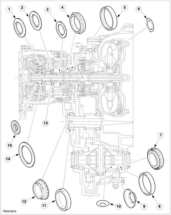
| Pos. | Spare Part No | Name |
| 1 | - | Thrust bearing No.3 rear planetary sun gear assembly |
| 2 | - | Thrust bearing assembly No.5 sun gear front planetary gear |
| 3 | - | Thrust bearing assembly No.6 of the front planet carrier |
| 4 | - | Main shaft bearing inner race complete with rollers (2 pcs.) |
| 5 | - | Main shaft bearing outer race (2 pcs.) |
| 6 | - | Thrust washer of a support of the pump of a working liquid |
| 7 | - | Differential bearing inner race with rollers (2 pcs.) |
| 8 | - | Differential outer ring (2 pcs.) |
| 9 | - | Front axle differential side washer (2 pcs.) |
| 10 | - | Front axle differential bearing thrust washer (2 pcs.) |
| 11 | - | Transmission shaft roller bearing outer race (2 pcs.) |
| 12 | - | Transmission shaft inner race with rollers (2 pcs.) |
| 13 | - | Thrust bearing No.4 assy of rear planet carrier |
| 14 | - | Thrust bearing No.2 rear planetary sun gear assembly |
| 15 | - | Thrust bearing No.1 direct clutch cylinder assembly |
Range selection
The transaxle range selector has six positions: "P", "R", "N", "D", "2" And "1".
Position "R" manual gear lever
With the manual gear selector in position "R" no gear selected. The parking latch is manually engaged using the manual select lever cable and shift shaft.
For safety reasons, whenever the vehicle is parked, the parking brake must be applied.
Position "R" manual gear lever
With the manual gear selector in position "R" reverse gear selected. Reverse gear allows the vehicle to move in reverse with a reduced gear ratio.
Position "N" manual gear lever
With the manual gear selector in position "N" no gear selected. The transmission is not locked so the wheels can spin.
The car should be started in neutral gear.
Position "D" manual gear lever
With the manual gear selector in position "D" and with the O/D switch not pressed, the transmission control allows all gears to be selected. When the O/D switch is depressed, shifting to 4th gear is inhibited or the transmission shifts down to 3rd gear.
Position "1" manual gear lever
With the manual gear selector in position "1" only first gear is selected. In addition to the 1st gear single-acting clutch, the transmission control engages the reverse gear brake to bring in the engine braking effect when coasting.
If you move the manual gear selector to the position "1" when the vehicle speed is increased for 1st gear, the gearbox control will allow downshifting only after the appropriate vehicle speed has been reached.
Position "2" manual gear lever
With the manual gear selector in position "2" only second gear is selected. Transmission control does not allow shifting to 1st gear.
If you move the manual gear selector to the position "2" If the vehicle speed is increased for 2nd gear, the gearbox control will allow downshifting only after the appropriate vehicle speed has been reached.
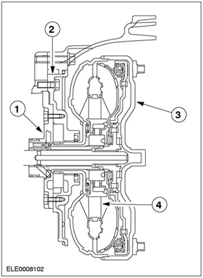
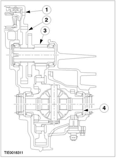
General overview of design and functions
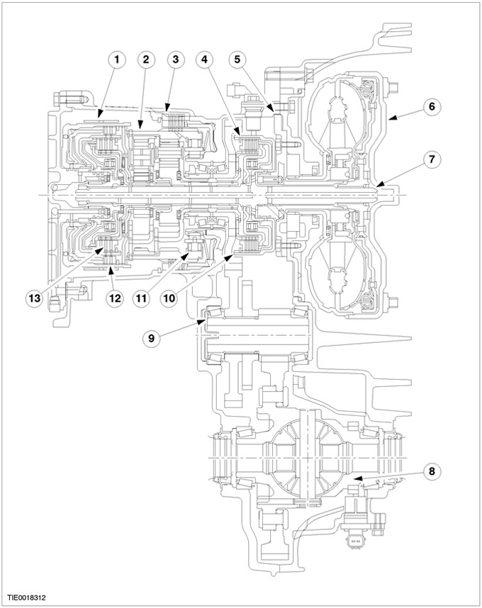
| Pos. | Spare Part No | Name |
| 1 | - | Intermediate/Overdrive Band Brake |
| 2 | - | Front ring gear planetary gear |
| 3 | - | Low/Reverse Clutch |
| 4 | - | Forward clutch |
| 5 | - | Fluid pump and torque converter stator support |
| 6 | - | torque converter |
| 7 | - | Transmission input shaft |
| 8 | - | Differential |
| 9 | - | Transmission shaft assembly |
| 10 | - | main drive gear |
| 11 | - | Low gear single acting clutch |
| 12 | - | Reverse clutch |
| 13 | - | Direct clutch |
Torque Converter and Torque Converter Lockup Clutch
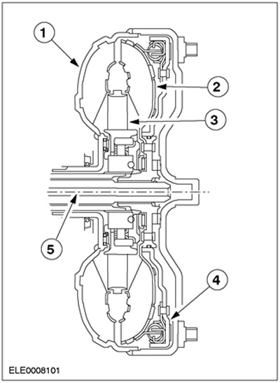
| Pos. | Spare Part No | Name |
| 1 | - | Torque converter housing and impeller |
| 2 | - | Turbine |
| 3 | - | stator |
| 4 | - | Torque converter lock-up clutch |
| 5 | - | Transmission input shaft |
The torque converter hydraulically transmits torque from the engine to the transmission input shaft.
The stator amplifies the torque applied to the input shaft (approximately 85% speed difference between impeller and turbine).
The stator for weight reduction is made of synthetic resin.
To increase the efficiency of the automatic transmission, the torque converter has a clutch. With the torque converter lock-up clutch locked, torque is transmitted directly from the crankshaft through the torque converter housing to the transmission input shaft.
In 3rd and 4th gear, the torque converter clutch is hydraulically activated by the PCM by actuating the solenoid valves in the valve block. Clutch engagement depends on throttle position, vehicle speed, and manual gear lever position.
Oil pump and stator support
| Pos. | Spare Part No | Name |
| 1 | - | Stator support |
| 2 | - | Working fluid pump |
| 3 | - | impeller torque converter |
| 4 | - | stator |
The hydraulic fluid pump is a crescent-shaped gear pump, directly driven by the crankshaft via drive elements located on the hub of the torque converter impeller. The hydraulic fluid pump is bolted to the torque converter housing.
The stator support is part of the working fluid pump. Splines on the support define the position and hold the torque converter stator.
Planetary gear
The specific gears of the gearbox are shifted using the operation of two planetary gear stages located one behind the other.
Clutches and band brakes
The individual gear ratios are selected by means of four multi-plate clutches, a band brake and a single-acting roller clutch.
Elements are controlled by PCM using pulse-width modulated solenoid valves (PWM)
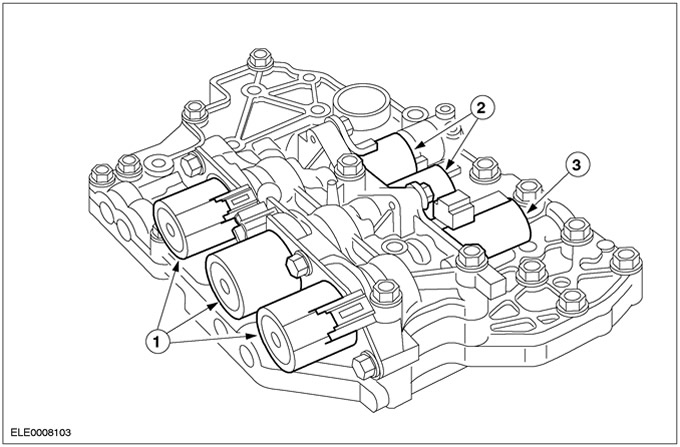
Valve block
| Pos. | Spare Part No | Name |
| 1 | - | PWM Solenoid Valves |
| 2 | - | Solenoid switching valves (on off.) |
| 3 | - | Main control valve (variable force solenoid - VFC) |
The valve block contains six solenoid valves:
- three PWM solenoid valves (solenoid valves with pulse width modulation),
- two switching solenoid valves (on off.),
- one main control valve (variable force solenoid valve).
Separate clutches and band brakes receive pressure from PWM solenoid valves and shift solenoid valves (on off), and so the gear changes.
PWM solenoid valves allow for direct engagement of clutches and brakes to provide very smooth shifting by making precise pressure adjustments.
Shift Solenoid Valves (on off) divert hydraulic flow to clutches and band brakes, thus reducing the number of modulating valves required. Main control valve (variable force solenoid valve) ensures that sufficient hydraulic pressure is available under all operating conditions.
Solenoid valves PWM No. 1-3
Solenoid valves PWM 1, 2 and 3 control the pressure applied to the band brakes and clutches.
Solenoid switching valves (on off.) Nos. 1 and 2
Shift Solenoid Valves (on off) switches various oil passages in the valve block to apply pressure to individual clutches and band brakes.
The use of shift solenoid valves is necessary for direct actuation of individual clutches and band brakes.
Main control valve
Main control valve (variable force solenoid valve) controls the main line pressure required for individual transmission ranges.
The pressure in the main line is regulated depending on the current engine load.
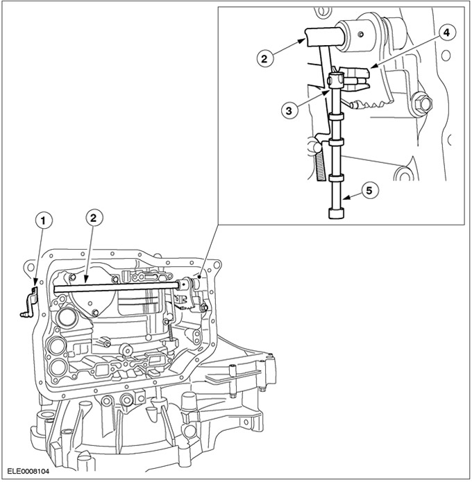
Internal switching mechanism
| Pos. | Spare Part No | Name |
| 1 | - | Lever on hand shaft |
| 2 | - | hand shaft |
| 3 | - | Stand-night latch actuation lever |
| 4 | - | Manual valve actuating lever |
| 5 | - | Manual valve (in a valve block not shown) |
The shift lever is fixed on the section of the manual shaft, which has a square section. The axial movement of the select lever cable is converted into rotation of the hand shaft.
In the transmission, the hand shaft operates the park latch actuation lever and the manually operated valve actuating lever. A manually operated valve is a valve operated entirely by hand; it is moved by a manually operated valve actuating lever located in the valve block.
A manually operated valve guarantees operation when the hydraulic emergency program is active.
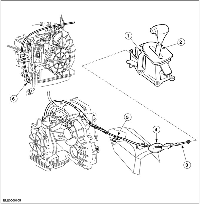
External Gear Shifter
| Pos. | Spare Part No | Name |
| 1 | - | Select lever assembly |
| 2 | - | Selection lever |
| 3 | - | Select lever cable |
| 4 | - | guide |
| 5 | - | clamp |
| 6 | - | Lever on shift shaft |
The manual selector lever cable on the transmission side connects to the ball on the lever located on the handshaft.
The cable supports are attached to the gearbox housing and then attached to the manual select lever bracket.
The manual select lever cable adjuster is located on the cable sheath on the transmission side.
On the side of the manual select lever, the cable is clamped in the ball.
Intermediate gear and main gear assy
| Pos. | Spare Part No | Name |
| 1 | - | main drive gear |
| 2 | - | Transmission shaft drive gear |
| 3 | - | Driven gear of the transmission shaft |
| 4 | - | Differential |
The final drive gear is splined to the carrier of the front planetary gear and drives the intermediate gear drive gear.
The driven gear of the transmission shaft drives the final drive assembly. Through the main gear, the torque is transmitted to the axle shafts. The differential compensates for the difference in the frequency of rotation of the axle shafts.
The intermediate gear is designed so that the gear ratio of the main gear can be adapted to the specific needs of using an automatic transmission with various engines.
Gearbox control overview
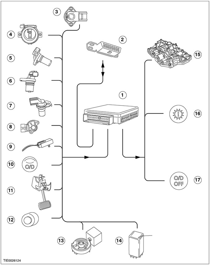
| Pos. | Spare Part No | Name |
| 1 | - | PCM EEC V |
| 2 | - | Data link connector (DLC) |
| 3 | - | Throttle position sensor (TR) |
| 4 | - | Mass air flow sensors (MAF) and air intake temperature (IAT) |
| 5 | - | crankshaft position sensor (CKP) |
| 6 | - | Secondary shaft speed sensor (OSS) |
| 7 | - | Turbine shaft speed sensor (TSS) |
| 8 | - | Transmission range sensor (TR) |
| 9 | - | Transmission fluid temperature sensor (TFT) |
| 10 | - | overdrive switch (O/D) |
| 11 | - | Stoplight switch |
| 12 | - | Select Lever Shift Lock Solenoid Valve |
| 13 | - | Ignition key lock solenoid |
| 14 | - | Air conditioning relay |
| 15 | - | Solenoid valves in the valve block |
| 16 | - | Control lamp of the power unit on the instrument panel |
| 17 | - | Control lamp O/D on the instrument panel |
Powertrain control module (RSM)
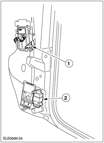
| Pos. | Spare Part No | Name |
| 1 | - | PCM EEC V |
| 2 | - | Inertial fuel cut-off (IFS) |
The PCM is located under the trim panel on the right pillar "A". On vehicles with automatic transmission, PCM EEC V controls the transmission as well as the engine management system. In this case, a module with a 104-pin connector is used.
The PCM evaluates the input signals from the individual sensors and actuates the solenoid valves in the transmission valve block exactly according to the operating condition.
Transmission diagnostic tests can be performed via the data circuit connector (DLC), located above the central electrical junction box (CJB).
Emergency work program
If, due to incorrect signals, correct shifting cannot be guaranteed, the PCM starts in the emergency operating program mode.
The driver learns about the action of the emergency operating program by lighting up the control lamp of the power unit on the instrument panel. Continuous monitoring is guaranteed in the following limited states:
- maximum pressure in the main line;
- 3rd gear with the manual gear lever in the positions "D", "2" And "1" without engaging the locking torque converter clutch;
- reverse gear with the manual gear selector in position "R".
Visitor comments