Diagnostic strategy
Troubleshooting for an electronically controlled automatic transaxle has been simplified with a proven diagnostic technique. One of the most important things to remember is that there are special procedures that must be followed.
NOTE: Do not take so-called shortcuts and do not rely on critical checks and adjustments already being made.
Follow the procedures in the order in which they are presented. This will allow you not to miss the most important stages of diagnostic actions.
To correctly diagnose the problem, the following editions are offered:
- Engine Management/Emissions System Diagnostic Guide (PCED).
- TSB and OASIS messages.
- Schemes of electrical connections.
These publications provide the information you need when diagnosing transaxle problems. Use the diagnostic flowchart as a guide and follow the prescribed sequence.
Preview
- Knowledge and understanding of the client's problem.
- Validation of the validity of the customer's complaint by performing a test drive / operating the problematic vehicle system
- Checking the level and condition of the working fluid
- Checking for Optional Accessories Not Factory Installed
- Checking the correct adjustment of the switching mechanisms
- Checking TSB bulletins and OASIS messages related to the issue under consideration
Diagnostics
- Perform the OBD procedures with the ignition on and the engine off (KOEO) and with the ignition on and the engine running (KOER).
- Write down all diagnostic trouble codes (DTC).
- First, work out the actions for codes that are not related to the gearbox.
- Then work out the actions on the codes related to the gearbox.
- Erase all permanent codes and try to reproduce them.
- Work out actions on permanent codes.
- If you only receive pass codes, for more information and diagnostic guidance, go to the Symptom Diagnostic Index.
Follow the diagnostic sequence to diagnose and fix the problem the first time.
Diagnosis Flowchart
|
Check |
Result |
Actions |
|
Knowledge and understanding of the client's problem |
||
|
Checking the level and condition of the working fluid |
||
|
Validation of the validity of the customer's complaint by performing a test drive / operating the problematic vehicle system |
||
|
Checking for optional non-factory installed accessories and verifying correct installation |
||
|
Checking Gear Shift Lever Adjustment |
||
|
Checking technical service bulletins and OASIS messages for descriptions of vehicle problems |
||
|
Perform a quick check, both KOER and KOEO |
||
|
Write down all codes |
||
|
1) Did you record any diagnostic trouble codes? |
Yes |
Perform the necessary actions for all serious diagnostic codes. Practice Pinpoint tests. Refer to the PCED first, then the workshop manual. |
|
No |
For more information, refer to Symptom Diagnosis available in this section. then GO to step 5. |
|
|
2) Are there any permanent codes in memory? |
Yes |
Erase codes and run a drive cycle test. |
|
No |
GO to step 4. |
|
|
3) Permanent codes reappear? |
Yes |
Work out the necessary actions for all permanent codes. Run Pinpoint tests. Refer to PCED, then Transaxle Manual, then Workshop Manual, then GO to step 4 |
|
No |
GO to step 4. |
|
|
4) The problem is resolved? |
Yes |
Perform a final quick check to ensure that no DTCs are present. Erase codes from memory. Return the vehicle to the customer. |
|
No |
For more information, refer to Symptom Diagnosis available in this section. |
|
|
5) Are there any electrical problems? |
Yes |
Install the scan tool and perform the output state control check, then GO to step 6. |
|
No |
Refer to the hydraulic and mechanical programs to diagnose and correct the problem, then GO to step 7. |
|
|
6) Was the transaxle issue fixed after the scan tool was installed? |
Yes |
Refer to PCED, Intermittent Troubleshooting section, and use a scan tool to diagnose the cause of the problem in the processor, vehicle wiring harness, or external input devices (sensors or switches). |
|
No |
Refer to the hydraulic and mechanical programs to diagnose and correct the problem, then GO to step 7. |
|
|
7) The problem is resolved? |
Yes |
Perform a final quick check to ensure that no DTCs are present. Erase codes from memory. Return the vehicle to the customer. |
|
No |
Get Help with the Help Desk ("hotline"). |
Preview
Before starting diagnostic procedures, check the following points:
Knowledge and understanding of the problem
To properly diagnose a problem, first understand the customer's complaint or problem state. Direct contact with the client may be required to begin testing the legitimacy of a client's complaint. Identify the conditions under which the problem occurs, for example:
- hot or cold vehicle components,
- high or low outside temperature,
- driving conditions,
- loaded or unloaded car.
After understanding when and how the problem manifests itself, move on to verifying the validity of the complaint.
Status check
This section provides information on what to use both when determining the actual cause of customer complaints and when performing the appropriate procedures. The following procedures should be used to validate customer complaints about an engine.
Determining the customer's problem
NOTE: Some transaxle conditions can lead to engine problems. Lack of torque converter clutch engagement will result in engine stalling.
Identify customer problems related to vehicle use and traffic conditions, paying attention to the following points:
- high or low vehicle operating temperature,
- high or low outside temperature,
- nature of the area
- loaded or unloaded car,
- driving in the city or on the freeway,
- switching to a higher gear (up),
- downshifting (down),
- inertia motion,
- engagement,
- noise/vibration - check for dependence either on the speed of the crankshaft, or on the speed of the car, or on the gear shift, or on the selected gear, or on the selected range, or on the temperature.
Liquid level check
Under normal conditions, there is no requirement to check the transmission fluid level in the transaxle transaxle. However, if the transaxle is not working properly, is slipping, shifting is slow, or there is any sign of fluid leakage, the fluid level should be checked.
WARNING: The vehicle should not be driven if the transmission fluid level is below the lower line on the dipstick and the outside temperature is above 10°C (50°F).
NOTE: Transmission fluid expands when heated To accurately check the fluid level, drive the vehicle until normal operating temperature is reached, approximately 30 km (20 miles).
NOTE: If the vehicle has been driven for an extended period at high speeds, in hot weather urban driving, or has towed a trailer (trailer), it should be shut off for approximately 30 minutes to allow the working fluid to cool before checking.
NOTE: Incorrect transmission fluid level can affect the operation of the transaxle and may result in damage to the transaxle. Refer to the procedures in this section to properly check and top up the transaxle fluid level.
1. Drive a car for 30 km (20 miles) or until the vehicle reaches normal operating temperature.
2. Park the vehicle on a level surface and apply the parking brake.
3. Place your foot on the brake pedal, start the engine and move the range selector lever through all gear ranges. Allow sufficient time to engage each gear.
4. Set the range switch to "P" (parking gear) and leave the engine running.
5. Remove the transmission fluid dipstick and wipe it with a clean, lint-free cloth.
6. Install the dipstick of the fluid level indicator, making sure that it is firmly seated in the filler tube.
7. Remove the dipstick of the liquid level indicator. The liquid level must be within the designated area.
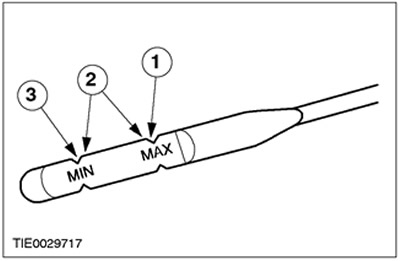
| Position | Name |
| 1 | Maximum fluid level |
| 2 | Normal operating temperature for liquid level check 66°C-77°C (150°F-170°F) |
| 3 | Minimum fluid level |
High fluid level
If the liquid level is too high, air may saturate the liquid. This is due to the agitating action of the rotating internal parts. This leads to erratic control pressure fluctuation, foaming, fluid leakage from the vent pipe, and may damage the transaxle unit. If overflow is observed, correct the fluid level.
Low fluid level
A low fluid level can result in poor gear engagement in the transaxle, slippage or damage. It may also indicate the presence of leaks through one of the seals or gaskets of the gearbox in the block with the drive axle.
Adding transmission fluid
CAUTION: The use of any other type of transaxle transaxle fluid than specified may damage the transaxle transaxle.
If transmission fluid needs to be topped up, top up in 0.25 l increments (1/2 pint) through the oil filler pipe. Do not overfill with liquid. Refer to table for information on transmission fluid type "General specifications", presented in this section.
Checking the condition of the transmission fluid
1. Check fluid level. For more information, see Chap. "Liquid level check", presented in this section.
2. Check the color and smell. The color under normal conditions should be reddish, but not brown or black.
3. Let the liquid drip onto a paper towel and look at the stain.
4. If solid particles are found, remove the transaxle oil pan for a closer inspection.
5. If the contamination of the transmission fluid or damage to the transaxle transaxle is confirmed by the presence of sediment on the bottom of the oil pan, the transaxle transaxle should be disassembled and completely cleaned.
6. Perform diagnostic checks and adjustments. For more information, refer to Symptom Diagnosis available in this section.
Road test car
NOTE: Always use a safe driving style based on traffic conditions and respecting the Rules of the Road.
The Road Test Shift Check and Torque Converter Clutch Function Test provide diagnostic information about the transaxle shift controls and torque converter operation.
Checking shift points during a road test
This test confirms that the shift control system is operating correctly.
- 1. Bring the engine and transaxle to normal operating temperature.
- 2. Drive the vehicle with the gear selector in the «D» (overdrive switch on).
- 3. Open the throttle as low as possible and watch the speeds at which the upshift occurs and the torque converter engages. Refer to the following table for shifting speeds for the appropriate final drive ratios (FDR). (See also brochure «Specifications of the automatic transmission in the block with the leading axle».)
- 4. Stop the vehicle. Select position «D» (overdrive switch off). Repeat step 3. The transaxle will perform all upshifts except upshifts from third to fourth gear, and the torque converter clutch should engage at speeds above 80 km/h (50 mph).
- 5. Depress the accelerator pedal to the floor - wide open throttle condition (WOT). The gearbox in the block with the leading axle should switch from third gear to second, or from third to first, depending on the speed of the vehicle. The torque converter clutch should also come loose.
- 6. When the vehicle speed is over 48 km/h (30 mph) move the gear selector out of position «D» into position «1» and release the accelerator pedal. The transaxle should immediately downshift to second gear. When the vehicle speed drops below 32 km/h (20 mph), the transaxle should shift down into first gear.
- 7. If the transaxle cannot upshift/downshift or the torque converter clutch does not engage/disengage. Refer to Symptom Diagnosis in this section for more information. - possible reasons.
Table of speeds at which gear shifting occurs
|
Throttle Position |
Shift gears |
Final drive ratio 3.67:1 |
Final drive ratio 3.90:1 |
Final drive ratio 4.15:1 |
|||
|
km/h |
mph |
km/h |
mph |
km/h |
mph |
||
|
Closed |
4-3 |
35-19 |
22-12 |
35-19 |
22-12 |
30-20 |
48-32 |
|
Closed |
3-2 |
19-3 |
12-2 |
19-3 |
12-2 |
35-19 |
22-12 |
|
Closed |
2-1 |
19-3 |
12-2 |
19-3 |
12-2 |
51-35 |
32-22 |
|
Minimum PID monitoring voltage TP = 1.25V |
1-2 |
12-28 |
8-18 |
11-27 |
7-17 |
11-27 |
7-17 |
|
Minimum PID monitoring voltage TP = 1.25 V |
2-3 |
27-43 |
17-27 |
24-40 |
15-25 |
24-40 |
15-25 |
|
Minimum PID monitoring voltage TP = 1.25V |
3-4 |
43-59 |
27-37 |
37-53 |
23-33 |
31-51 |
22-32 |
|
wide open |
1-2 |
41-57 |
26-36 |
45-61 |
28-38 |
43-59 |
27-37 |
|
wide open |
2-3 |
88-104 |
55-65 |
96-112 |
60-70 |
88-104 |
55-65 |
|
wide open |
3-4 |
123-140 |
77-87 |
135-151 |
84-94 |
138-154 |
86-96 |
Torque Converter Diagnostics
Before installing a new torque converter, all diagnostic procedures should be worked out. This is necessary to prevent the unreasonable installation of new or remanufactured torque converters. Only after a complete diagnostic evaluation can a decision be made to install a new torque converter. Start with common diagnostic procedures such as:
1. Preview
2. Knowledge and understanding of the client's problem
3. Check the validity of the complaint - check the operation of the torque converter clutch; refer to ch. "Checking the operation of the torque converter" in this section.
4. Perform diagnostic procedures.
- Perform on-board diagnostics, refer to Ch. "On-board diagnostics using diagnostic equipment" in this section.
- Perform a line pressure test; refer to ch. "Line pressure check" in this section.
- Perform an engine speed limit check; refer to ch. "Checking the engine speed limit" in this section.
- Troubleshoot all DTCs that are not related to the transaxle unit first.
- Troubleshoot any DTCs associated with the transaxle transaxle.
- Perform on-board diagnostics to verify repairs completed.
- Run a symptom checklist. For more information, refer to Symptom Diagnosis available in this section.
- Use the index to find the appropriate program that best describes the feature (signs) malfunctions. The program will list all possible elements that may be causing or contributing to the problem. Check each item listed and perform any necessary diagnostics and repairs before replacing the torque converter.
Checking the operation of the torque converter
This check verifies that the torque converter clutch control system and torque converter are operating correctly.
1. Carry out an online check, refer to chap. "On-board diagnostics using diagnostic equipment" in this section. Check for DTCs. Refer to the DTC table.
2. Connect a tachometer to the engine.
3. Bring the engine to normal operating temperature by driving the vehicle at highway speed for approximately 15 minutes with the transmission in O/D.
4. After reaching normal operating temperature, maintain a constant vehicle speed of approximately 80 km/h (50 mph) and lightly hit the brake pedal with your left foot.
5. With a slight impact on the brake pedal, the engine speed should increase, and then five seconds after the brake pedal is released, it should decrease. If this does not happen, please refer to "Problems in the operation of the torque converter" in ch. "Symptom List Diagnosis".
6. If the engine stalls in O/D or manual 2 while idling with the vehicle stationary, move the selector lever to manual 1. If the engine stalls, refer to sec. "Problems in the operation of the torque converter" in ch. "Symptom List Diagnosis". Make repairs if necessary. If the engine does not stall in the O/D position. For more information, refer to Symptom Diagnosis available in this section.
Visual inspection
This inspection allows you to identify changes or additions made to the vehicle's systems that can affect the diagnosis. Inspect the vehicle for non-Ford factory installed options. These include:
Additional electronic elements:
- air conditioning system,
- generator,
- engine turbocharger,
- cellular telephone,
- Cruise control,
- SW radio,
- linear amplifier,
- reverse alarm,
- computer.
Vehicle modification:
These items, if installed incorrectly, will affect the operation of the powertrain control module (RSM) or gearboxes in a block with a driving axle. Pay particular attention to extra connections in the PCM or transaxle wiring harnesses, abnormal tire sizes, or changes in the drive axle ratio.
leaks; refer to p. "Inspection for leaks" in this section.
Correct adjustment of the lever mechanism; refer to Section 307-05.
Checking the gear lever mechanism
Check the adjustment of the gear lever mechanism by aligning the marks on the gear range selection lever in the block with the drive axle with the marks on the gearbox in the block with the drive axle. If the marks match, the fault lies in the indicator. Do not adjust the shift linkage.
A hydraulic leak in the mechanical control valve area can cause delayed engagement and slippage during operation if the linkage is not properly adjusted; refer to Section 307-05 for shift linkage adjustment.
Checking TSB Bulletins and OASIS Messages
Refer to all technical service bulletins and OASIS messages that deal with transaxle problems and follow the prescribed procedure.
Perform on-board diagnostics (KOEO, KOER)
After a road test, with the vehicle warm, and before disconnecting any connectors, perform a quick check using a scanner. Refer to PCED for diagnostics and testing of the powertrain control system.
Diagnostics
Special tool:
 | 418-F224 Worldwide Diagnostic System (WDS) , or equivalent scanner |
Diagnosing an automatic transmission with an electronically controlled transaxle is facilitated by using the following procedures. It is important to remember that there is a specific procedure that must be followed. Do not skip any steps or assume that important checks or adjustments have already been made. Follow the procedures in the order in which they are described. This will allow you not to miss the most important stages of diagnostic actions. By following a sequence of diagnostic procedures, the mechanic will be able to diagnose and fix the problem the first time.
On-board diagnostics using diagnostic equipment
NOTE: For detailed instructions and other methods of diagnosing using a scanner, contact the tester and PCED.
These online checks should be used to diagnose the powertrain control module and should be performed in order.
- Operational Check 1.0 - Visual Inspection
- Online Check 2.0 - Setup
- Operational Check 3.0 - Ignition on, engine off
- Online Check 4.0 - Persistent Memory
- Operational Check 5.0 - Ignition on, engine running
- Special Check Mode
- Deviation Check Mode
- Output test mode
- PCM reset mode
- Clearing DTCs
- OBD II driving cycle
- Other Scanner Resources
Refer to PCED for more information on other scanner diagnostic check resources. Other diagnostic methods include the following:
- Parameter identification access mode (PID)
- Data access mode "freeze frame"
- Oxygen sensor monitoring mode
Checking the movement cycle of the gearbox in the block with the driving axle
NOTE: Always use a safe driving style based on traffic conditions and respecting the rules of the road.
NOTE: The transaxle drive cycle check must be followed exactly. Transaxle transaxle failure must occur four times in a row for a shift fault DTC to be set, and five times in a row for a continuous torque converter clutch code to be set.
NOTE: When performing a transaxle drive cycle test, refer to the solenoid engagement table for proper solenoid operation.
After performing the online test, use the transaxle drive cycle test to check for continuous codes.
1. Write down and then erase the online verification codes.
2. Warm up the engine to normal operating temperature.
3. Make sure the transmission fluid level in the transaxle is correct.
4. When the gearbox is in the block with the drive axle in the position "O/D" at an average pace, accelerate from a stationary state to 80 km / h (50 mph). This will allow the transaxle to shift into fourth gear. Maintain a constant speed and keep the throttle open steadily for at least 15 seconds.
NOTE: PCA, EPC and VFS refer to electromagnets. PCA is preferred for this transmission because PCA is shown on the scanner display.
5. With the transaxle in fourth gear and maintaining a constant speed and throttle open stability, lightly depress and release the brake pedal to turn on the brake lights. Then hold the speed constant and the throttle steady for at least 5 seconds.
6. Brake to a complete stop and leave the vehicle stationary for at least 20 seconds.
7. Repeat the steps for p.p. 4 at least 6 times.
8. Perform a quick check and record the continuous DTCs.
After on-board diagnostics
NOTE: Vehicle wiring harnesses, powertrain control module, and sensors not associated with the transaxle can affect the transaxle operation. Fix such problems first.
After completing all the OBD procedures, troubleshoot any DTCs. Start with DTCs not related to the transaxle, then clear any DTCs related to the transaxle. Refer to the DTC table for status and symptom information. This table will prove helpful in linking to the correct manuals and assisting in diagnosing internal transaxle faults and external inputs not related to the transaxle. In the diagnosis of electrical faults, pinpoint tests are used. Verify that the diagnosis of the vehicle wiring harnesses and the PCM is also performed. PCED will assist in diagnosing electronic components that are not related to the transmission in the drive axle unit.
Before pinpoint tests
NOTE: Before entering the pinpoint tests, check the powertrain control module harnesses for proper connection, bent or broken pins, corrosion, loose wires, proper wiring, proper sealing, and general condition. Check the PCM, sensors and actuators for damage. Contact PCED.
NOTE: If the problem persists after diagnosing the electrical components. For more information, refer to Symptom Diagnosis available in this section.
If DTCs appear during on-board diagnostics, refer to the DTC table for the appropriate repair procedure. Before entering pinpoint tests, refer to any TSBs and OASIS messages for information on transaxle failures.
Visitor comments