Contents: Secondary shaft disassembly ↳ Disassembling the primary shaft ↳ Disassembling the differential ↳ Features of disassembling a… ↳
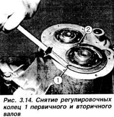
Place the washed gearbox on a disassembly stand. Remove the clutch release fork and bearing. Remove the rear cover of the gearbox housing and remove the adjusting rings of the primary and secondary shafts (Fig. 3.14).
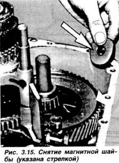
Unscrew the plug, remove the pin and the retainer spring. Unscrew the bolts securing the gearbox housing to the clutch housing. If necessary, hit the perimeter of the upper part of the housing with a plastic mallet (near the bearings and at the ends of the primary and secondary shafts. Remove the magnetic washer (Fig. 3.15); do not drop the washer, as it may break.
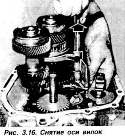
Remove the fork axle (Fig. 3.16) and its spring.
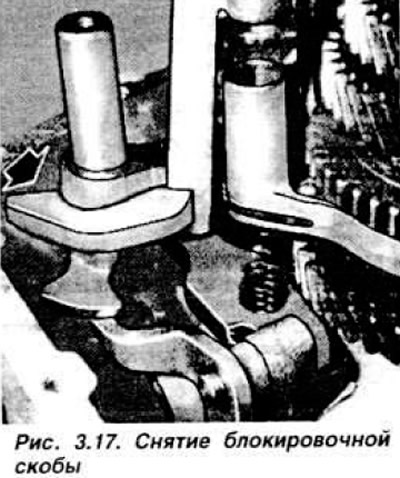
Remove the shift forks, then the locking bracket (Fig. 3.17).
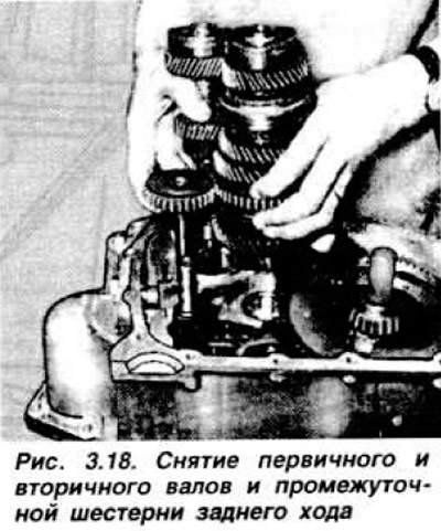
Remove the primary and secondary shafts and the reverse intermediate gear simultaneously (Fig. 3.18).
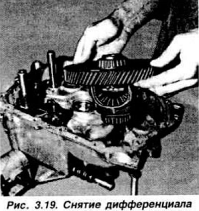
Remove the differential assembly (Fig. 3.19).
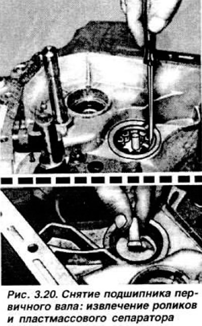
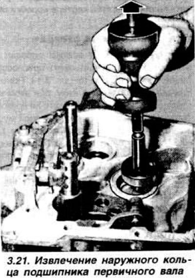
Remove the primary shaft bearing from the clutch housing in the following order: using a screwdriver, remove the bearing rollers one by one, then break the plastic separator (Fig. 3.20), using inertial puller 16.021 and 15.053, press out the outer bearing ring (Fig. 3.21).
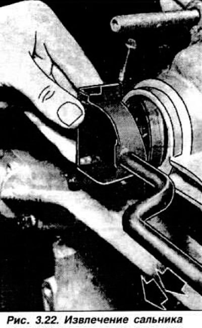
Press out the drive shaft seals, preferably using a special puller 21.051 (Fig. 3.22) and the outer rings of the differential bearings.
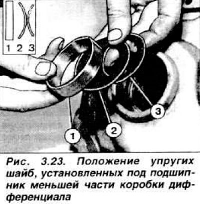
The outer ring of the bearing installed in the smaller part of the differential box rests against two elastic washers. It is necessary to remember their position: the smaller washer is installed with a stop on the seat, with the convex side to the convex side of the larger washer, the smooth side of which touches the outer ring of the bearing, as shown in Fig. 3.23.
Secondary shaft disassembly
Secure the secondary shaft in a vice with soft pads in a vertical position with support on the drive gear of the main transmission (Fig. 3.24).
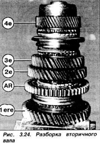
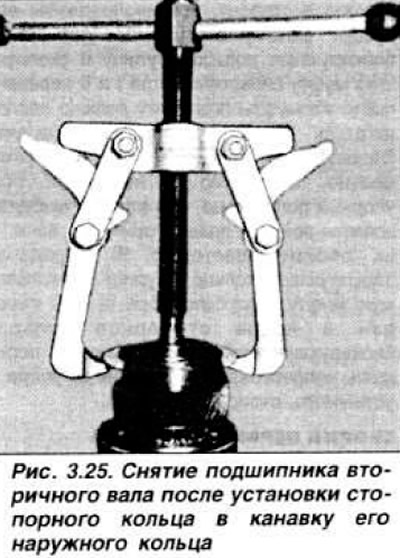
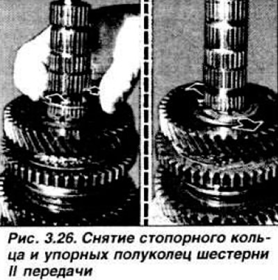
Remove and install in sequence: the retaining ring, the shaft bearing, having first installed the retaining ring in the groove (Fig. 3.25), the fourth gear pinion, the retaining ring, the hub and the synchronizer coupling of the third and fourth gears with blocking rings, the third gear pinion, the synchronizer blocking ring and the thrust half rings. the second gear pinion (Fig. 3.26), the hub and the synchronizer coupling of the first and second gears with blocking rings, the synchronizer hub retaining ring and the first gear pinion.
Disassembling the primary shaft
The primary shaft with gears is made of one piece, so only its bearings are removed using a universal two-lever puller. When removing the bearing from the IV gear side, insert the puller lever paws behind the adjusting ring installed in the groove of the outer bearing ring.
Disassembling the differential
Remove the technological mandrels for holding the planetary gears and extract these gears by tilting the differential box. Remove the retaining ring of the satellite axle and extract the satellites. Using a universal two-lever puller, press out the bearings, put marks on them so that they can be installed in their original places during assembly. Remove the speedometer drive gear. Unscrew the bolts securing the driven gear of the main gear and remove it, using a plastic mallet if necessary. Remember the position of the gear on the box: the bevel of the teeth towards the differential.
Features of disassembling a five-speed gearbox
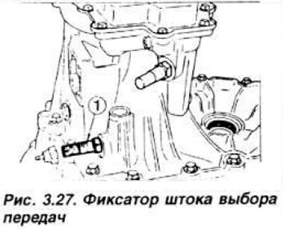
After removing the clutch release fork and bearing, unscrew the lock 1 (Fig. 3.27) of the gear selection rod, remove the lock pin and spring. Unscrew the locks carefully, as they are spring-loaded.
NOTE: Beginning with the 1984 model year, all Escorts with four- and five-speed transmissions were equipped with phosphated detents to aid in shifting when the transmission was hot. These detents are painted black instead of the steel color of the old detents.
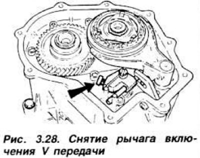
Unscrew ten bolts and remove the gearbox cover. Remove the 5th gear engagement lever (Fig. 3.28).
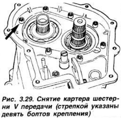
Remove the retaining ring and the 5th gear pinion, as well as the synchronizer and the 5th gear engagement fork assembly. Remove the retaining ring and the 5th gear pinion from the primary shaft using puller 16.035. Discard the retaining ring. Unscrew the nine bolts securing the 5th gear housing (Fig. 3.29) and remove it.
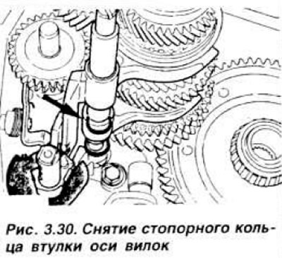
Remove the retaining rings of the secondary and primary shaft bearings. Unscrew the three nuts securing the gearbox bracket and remove the bracket. Remove the magnetic washer, remove the retaining ring from the fork axle bushing (Fig. 3.30), remove the 1st and 2nd gear shift fork, and remove the bushing.
Remove the primary and secondary shafts and the reverse intermediate gear simultaneously. Remove the locking bracket. Remove the differential case assembly.
[Content was created using data from this website: Fordbook.ru]