Contents: Secondary shaft assembly ↳ Assembling the primary shaft ↳ Differential assembly ↳ Installation of shafts and gear… ↳
Thoroughly clean and check the technical condition of the gearbox parts, taking into account the following:
- if a defect is detected on one of the elements of the primary shaft, replace the primary shaft;
- in case of re-installation of bearings, do not disassemble them (outer and inner rings);
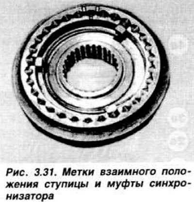
- in case of disassembling the synchronizer, make sure that before removing the sliding sleeve from the hub, that they are marked with relative positions (Fig. 3.31). Otherwise, make the necessary marks;
- store synchronizer locking rings together with the corresponding gears;
- do not use sharp tools or metal blades to clean the joint surfaces of aluminum alloy housings. Use rags soaked in solvent or trichloroethylene.
Secondary shaft assembly
Assembly is performed in the reverse order of disassembly. The 1st gear pinion is successively installed on the pre-lubricated secondary shaft, with its conical surface facing the side opposite to the main gear pinion; locking ring, hub and sliding sleeve of synchronizer of 1st and 2nd gears, groove of sleeve for fork should be located near gear of 1st gear; a locking ring, a new retaining ring, a 2nd gear pinion, both thrust half rings, with their projections fitting into the grooves of the secondary shaft, and their cage, a 3rd gear pinion, a locking ring, a hub and a sliding sleeve of the synchronizer of 3rd and 4th gears and a new retaining ring; locking ring, fourth gear pinion. Press the bearing until it stops and install the retaining ring.
Assembling the primary shaft
To install bearings, use pieces of pipe of the corresponding diameter, press them until they stop. Install the bearing with a groove on the side of the fourth gear pinion (the bearing of the larger diameter).
Differential assembly
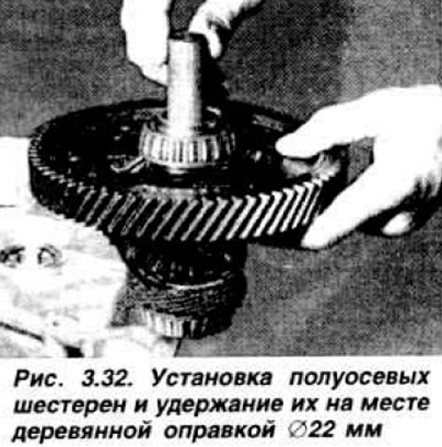
Install the speedometer drive gear. Pay attention to the position of its pin, using a 15.025 mandrel or a piece of pipe of the corresponding diameter, install the bearings in the differential box. Insert the axle. Install the satellites and retaining rings. Insert the half-axle gears through the cutouts in the box, seat them in place, paying attention to the correct seating, and install a plastic or wooden mandrel (Fig. 3.32).
Install the driven gear of the main transmission with the beveled part towards the differential box and secure it with new bolts, gradually tightening them to a torque of 9.8–12.8 kgf·m.
Installation of shafts and gear selection mechanism
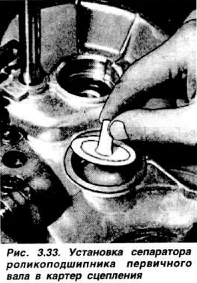
Install oil deflector 26 (into the bore of the clutch housing under the roller bearing of the primary shaft)fig. 3.7). Install the plastic separator (Fig. 3.33) until it touches the oil deflector, paying attention to its correct centering. Install the rollers in the separator.
Slightly punch the outer bearing ring around the circumference so that it does not rotate in the housing. Install the differential case with the speedometer drive gear facing down. Install the reverse intermediate gear by inserting the engagement lever pin into the annular groove of the gear. Simultaneously install the primary and secondary shafts into the housing, lifting the reverse intermediate gear upward so that it is above the 1st gear gear. Install spring 6 (Fig. 3.34) of the fork axle into the socket.
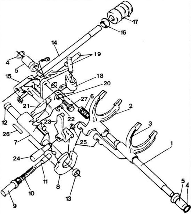 Fig. 3.34. Gear selection mechanism.
1 - shift fork axle; 2 — fork for shifting 1st and 2nd gears; 3 — fork for shifting III and IV gears; 4 — ring; 5 — bushing; 6 - spring; 7 — gear selection rod; 8 - locking bracket; 9 — retainer plug; 10 — retainer spring; 11 — retainer finger; 12 and 13 — gear selection rod bushings; 14 — intermediate gear selection shaft; 15 - leash; 16 — oil seal; 17 - protective cover; 18 — support for forward gear selection levers; 19 — axles; 20 and 21 — forward gear selection levers; 22 and 25 - retaining rings; 23 — reverse gear lever; 24 — reverse gear lever axis; 26 — pin.
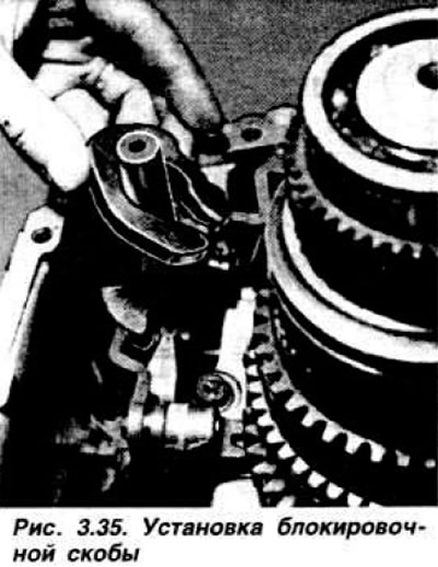
Install the locking bracket (Fig. 3.35) and gear shift forks.
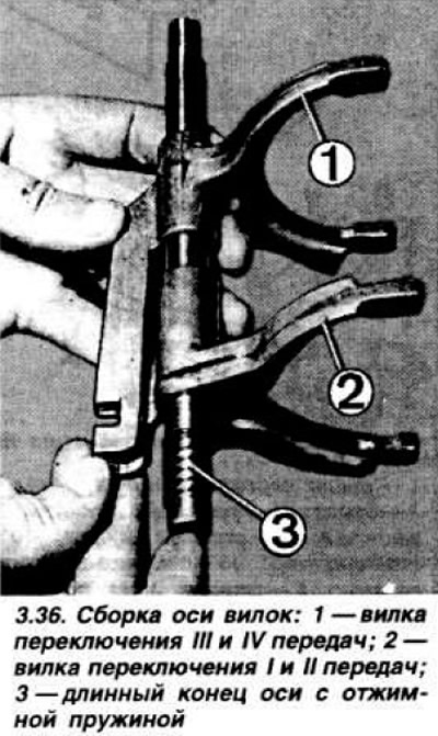
Align the half rings of the forks on one line (Fig. 3.36) and insert the fork axle 1 (Fig. 3.34) with the long end into the spring previously installed in the crankcase.
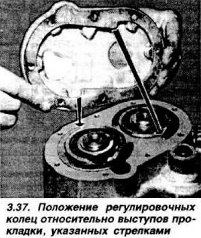
Check that all gears are engaged, leave 4th gear engaged for subsequent adjustment of the gearshift drive after installing the gearbox on the car. Install the magnetic washer in place and secure it with grease so that it does not shift during installation of the rear cover. Install the outer bearing ring in the rear part of the differential case, having first placed two elastic washers - the flat side of the smaller washer in the box socket, the flat side of the larger washer towards the bearing ring. Punch the bearing ring at two points. Apply a thin layer of oil to the plane of the housing joint, install the gasket and clutch housing using a plastic mallet. Gradually tighten the mounting bolts to a torque of 2.5 kgf·m. From three possible thicknesses, select adjusting rings so that they enter the grooves on the outer ends of the shafts without a gap, install them. lifting the shafts upward with a screwdriver. Position the adjusting rings in accordance with the cutouts of the gasket (Fig. 3.37) so that there is no overlap.
Install new gasket and rear cover Install pin, spring and plug of gear selector rod retainer Install clutch release bearing, fork and lever.
[This article was borrowed from the website: fordbook.ru]