Contents: Microswitches mounted on the… ↳ Microswitches installed under the… ↳ Speed control actuator ↳
1. This system is installed on some models upon request.
2. The layout of the system components is shown in Fig. 21.2. The system operates in the speed range from 40 to 200 km/h.
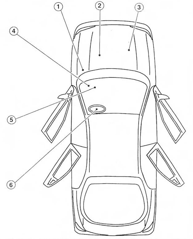 Fig. 21.2. Speed control system components (shown for left-hand drive models).
1. Electronic speed control device
2. Vehicle speed sensor
3. Throttle valve actuator
4. Interrupt relay (only for models with traction control system)
5. Microswitches for brake light, brake pedal and clutch pedal
6. Driver-operated steering wheel switches
3. The system comprises an electronic speed control device with a built-in actuator and a micro switch, installed in the engine compartment. The built-in actuator of the electronic device is connected by a cable to the actuator of the throttle valve. The system also comprises switches that are turned on by the driver, micro switches for the brake pedal and clutch pedal, an indicator and a vehicle speed sensor.
4. Driver-operated switches are mounted on the steering wheel and are used to control various functions.
5. The vehicle speed sensor, mounted on the transmission, provides AC voltage pulses to the electronic speed control unit. On early models, the sensor is connected to the speedometer drive cable. On later models, the electronic speedometer directly receives the speed sensor signal.
6. The brake light microswitch, the brake pedal microswitch and (if equipped) the clutch pedal microswitch are designed to disconnect the speed control system circuit. The brake light microswitch is switched on when the brake pedal is pressed smoothly, and the brake pedal microswitch is switched on when the pedal is pressed sharply.
7. When the system is operating, the indicator displayed on the instrument panel lights up.
8. The procedure for removing system components is described below. Before performing work, disconnect the negative battery cable (chapter 5A paragraph 1). Perform installation in the reverse order of removal.
Microswitches mounted on the steering wheel
9. Remove the airbag (paragraph 28).
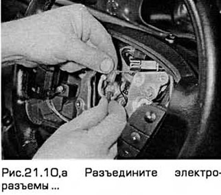
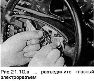
10. Disconnect the electrical connectors, remembering their position and the position of the wiring (see Fig. 21.10, a-c).
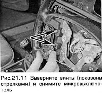
11. Then unscrew the screws and remove the microswitches (see Fig. 21.11).
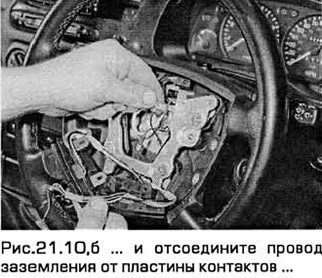
12. If necessary (for example, to access the horn switch), the contact plates and springs can be removed from the switches by unscrewing the screws.
Microswitches installed under the brake and clutch pedals
13. Remove the lower panel from the front panel, located under the steering column.
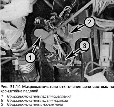
14. Disconnect the electrical connectors of the clutch pedal, brake pedal and brake light micro switches (see Fig. 21.14).
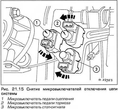
15. To remove the clutch and brake pedal microswitches, turn them counterclockwise. To remove the brake light microswitch, turn it clockwise (see Fig. 21.15).
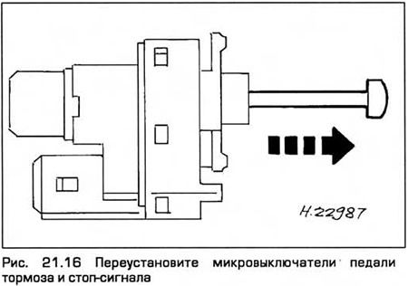
16. Installation - in the reverse order of removal. To ensure that the brake pedal microswitches function correctly, reinstall the microswitches by pulling out the plungers completely (see Fig. 21.16). Press the pedal so that the distance between it and the support bracket is as specified in Chapter 9. Holding the pedal in this position, securely fasten the microswitch and smoothly release the pedal until it reaches the stop. This automatically sets the microswitch position.
Speed control actuator
17. On models with 4-cylinder engines, remove the air cleaner (chapter 4).
18. Disconnect the actuator cable from the throttle linkage on the throttle body by freeing the cable end from the segment and unfastening the cable housing from the bracket.
19. On V6 models, disconnect the wiring harness electrical connector on the air cleaner top cover.
20. Disconnect the electrical connector of the assembly wiring. Unscrew the actuator mounting bolt. Then pull the actuator until its mounting pins come out of the holes.
21. Remove the assembly. On models with air conditioning, it may be necessary to unclip and remove the right section of the windshield deflector to access the assembly.
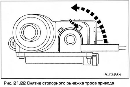
22. Press the locking lever of the drive cable cover and remove the cover by turning it counterclockwise (see Fig. 21.22).
23. Smoothly release the cable locking protrusion (no more than 0.5 mm) and push the cable tip out of the pulley slot.
24. When installing, make sure that the cable end is locked in the slot of the pulley.
25. To install the cable cover onto the actuator pulley, hold the cable taut in the pulley groove and pull on the cable end mounted on the throttle linkage to pull the cable cover onto the pulley.
26. To install the cable cover, hold the cable taut and hold the pulley. Then fit the tabs of the cable cover into the slots of the actuator. Turn the cover clockwise until the locking lever engages the stopper.
Note: Incorrect installation of the cable on the pulley may cause the idle speed to increase. After installing the actuator, make sure the throttle lever is in the idle position.
[The original can be found on the specified resource: FordBook.ru]