2. The system block together with the display are installed in a single module.
Maintenance interval indicator
3. The system contains an indicator that lights up when the vehicle has completed a run (or when the time is up), regulated by the maintenance schedule.
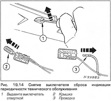
4. On pre-1996 models, to reset the indication and turn off the indicator, press the switch located inside the glove box and hold it for at least four seconds with the ignition on. On models manufactured since 1997, the switch is located on the instrument panel under the arrow symbol. It must be pressed with a thin rod and held for at least four seconds with the ignition on. If the car is under warranty, this operation must be performed by dealers.
Component Replacement
5. The procedures for removing components are described below. Disconnect the negative battery cable before performing the procedure. Installation is carried out in the reverse order of removal.
Display
6. Remove the dashboard bezel (paragraph 10).
7. Remove the screws, disconnect the electrical connectors and remove the assembly.
Display indicator lamp
8. Remove the display (see above).
9. Pull out the cover and remove the appropriate bulb and socket.
Bulb fault indication unit
10. From under a steering wheel remove facing from the front panel.
11. Unfasten the assembly and disconnect its electrical connector.
Maintenance Interval Reset Switch - Pre-1996 Models
12. Remove the glove box cover (chapter 11 paragraph 32).
13. Gently pry the sensor out with a small screwdriver.
14. Remove the back cover and disconnect the electrical connector (see fig. 19.14).
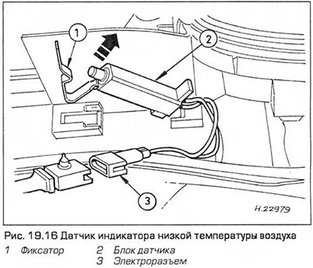
Low air temperature indicator sensor
15. Remove the front bumper.
16. Unfasten the sensor block and disconnect the electrical connector (see fig. 19.16).
Engine oil level sensor
17. Apply the parking brake, raise the front end and place it on supports.
18. Place a container under the sensor to catch oil smudges.
19. Turn out screws and remove a cover of the gauge.
20. Disconnect the electrical connector.
21. Turn out and remove the gauge. Remove Seal (see fig. 19.21).
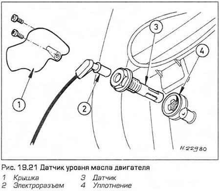
22. After installing the sensor, add oil to the engine (see "Weekly checks").
Open door alarm microswitch
23. Remove the door lock (chapter 11 paragraph 14).
24. Unfasten the sensor and disconnect the electrical connector.
Low Coolant Level Indicator Sensor
25 See chapter 3 paragraph 6.
Washer Fluid Low Indicator Sensor
26. Disconnect the electrical connector on the washer reservoir.
27. Syringe pump out the liquid from the tank.
28. Use a screwdriver to squeeze the sensor out of the tank (see fig. 19.28).
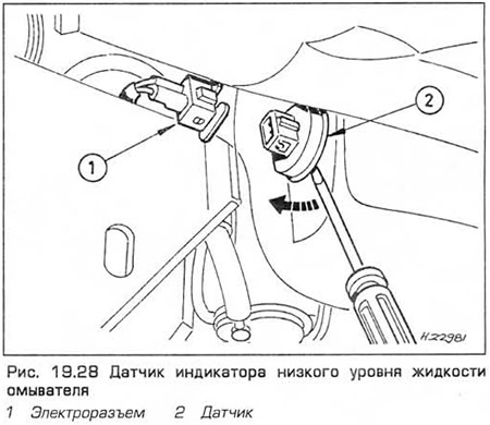
29. After installing the sensor, add fluid to the tank (see "Weekly checks").
Brake pad wear sensors
30. The sensor wires are in the material of the friction linings. When this material is worn, the wire "exposed" and contacts the brake disc, completing the brake pad wear indicator circuit. Damage to the insulation of the sensor wires can cause a false wear indicator signal.
Visitor comments