Contents: Removal ↳ Installation ↳
Removal
Front door exterior handle
1. Remove the door interior trim panel (paragraph 11).
2. Use a knife to cut the adhesive tape so that the foam insulator can be folded back to access the lock.
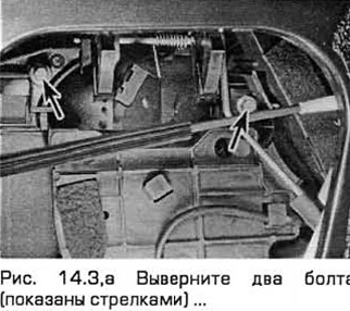
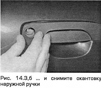
3. Unscrew the two bolts of the outer handle edging and remove the edging (see Fig. 14.3.a, b).
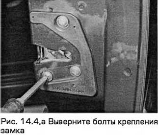
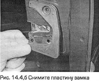
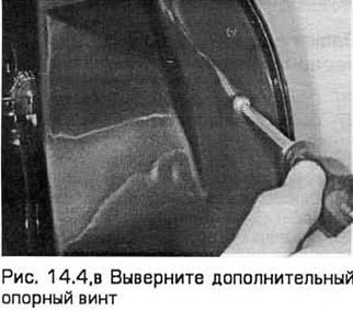
4. Unscrew the bolts securing the lock on the inside of the door at its rear edge. Remove the lock plate. Also unscrew the additional support screw (see Fig. 14.4, a-c).
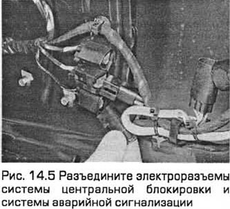
5. Unfasten and disconnect the wiring by disconnecting the electrical connectors of the central locking system and the hazard warning system (see Fig. 14.5).
6. Disconnect the door lock electrical connector.
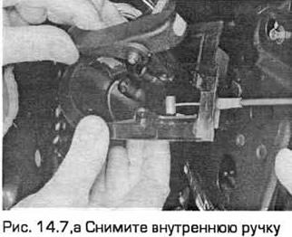
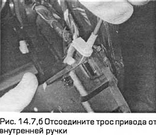
7. Disconnect the inner handle illumination lamp. Unscrew the screws and remove the inner handle. Disconnect the drive cable from the inner handle (see below) (see Fig. 14.7,a,b).
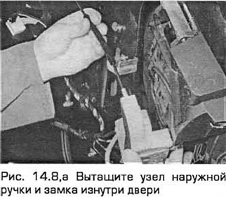
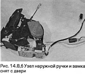
8. Disconnect the electrical connectors of the alarm and central locking systems by turning the lock assembly and handle. Pull the assembly out from inside the door (see Fig. 14.8,a,b).
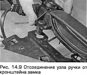
9. To disconnect the handle assembly from the lock bracket, push the rubber tabs inward and push the assembly out (see Fig. 14.9).
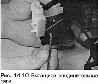
10. To remove the handle itself, turn the handle a quarter turn and pull out the connecting rods (see Fig. 14.10).
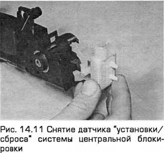
11. Remove the hazard warning light sensor and the central locking system set/reset sensor (see Fig. 14.11).
Rear door outer handle
12. Remove the inner door trim panel (paragraph 11).
13. Use a knife to cut the adhesive tape so that the foam insulator can be folded back to access the lock.
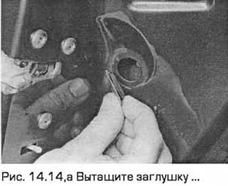
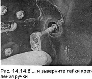
14. Pull the plug out of the rear edge of the door. Then unscrew the handle mounting nuts (see Fig. 14.14,a,b).
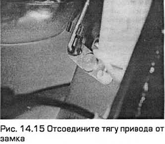
15. Remove the retainer and disconnect the drive rod from the lock (see Fig. 14.15).
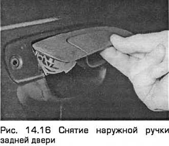
16 Remove the handle from the outside of the door (see Fig. 14.16).
Inner handle
17. Remove the door interior trim panel (paragraph 11).
18. Use a knife to cut the adhesive tape so that the foam insulator can be folded back to access the lock.
19. Disconnect the interior handle illumination lamp.
20. Remove the screws and remove the inner handle.
21. To remove the cable, first pull back the plastic end of the cable sheath and the plug. Press down lightly on the drive lever (in the lever lock position) until the cable aligns with the cable release slot at the bottom of the cable holder.
22. Knock out the cable bushing and disconnect the cable. Remove the handle assembly.
Lock cylinder
23. Remove the outer handle (see above).
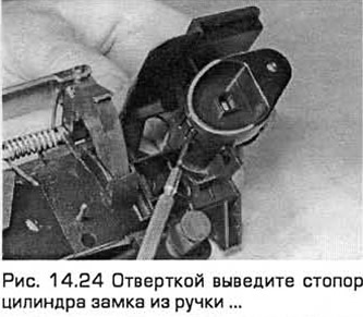
24. Use a screwdriver to remove the lock cylinder stopper from the handle (see Fig. 14.24).
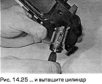
25. Insert the key into the lock and turn it so that it engages with the cylinder, then pull out the cylinder (see Fig. 14.25).
Electric lock motor - front door
26. Remove the outer handle (see above).
27. Release the drive rod from the retainer and pull it out.
28. Separate the drive rod from the plastic sleeve by turning it a quarter turn.
29. Release the sensor wiring from the retainer.
30. Disconnect the support plate from the lock.
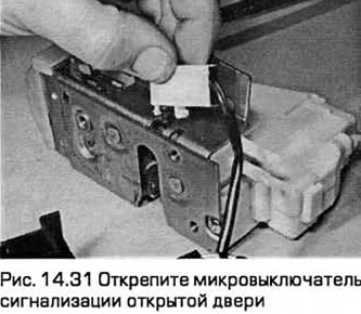
31. Release the open door alarm microswitch from the retainer (see Fig. 14.31).
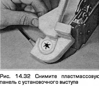
32. Press and remove the plastic panel from the mounting lug (see Fig. 14.32).
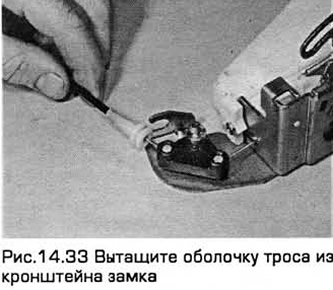
33. Pull the cable housing out of the lock bracket (see Fig. 14.33). Then rotate the cable a quarter turn to remove it from the crank.
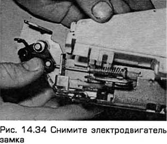
34. Unscrew the mounting screws and remove the lock electric motor (see Fig. 14.34).
Electric lock motor - rear door
35. Remove the outer handle (see above).
36. Remove the three lock mounting screws.
37. Release the sensor wiring from the clips holding it to the door.
38. Disconnect the door lock electrical connector.
39. Disconnect the interior handle illumination lamp.
40. Remove the screws and remove the inner handle.
41. Remove the lock assembly.
42. Release the open door alarm microswitch from the retainer.
43. Press and remove the plastic panel from the mounting tab.
44. Pull the cable housing out of the lock bracket. Then rotate the cable a quarter turn to remove it from the crank.
45. Remove the mounting screws and remove the lock motor.
Latch
46. Use a pencil to mark the position of the latch.
47. Remove the slotted head mounting screws and remove the latch.
Door retainer
48. Disconnect the negative battery cable.
49. Remove the assembly's mounting screws. On the front door it is secured with two screws, on the rear door - with one.
50. Pull the rubber bushing out of the door opening. Then unscrew the fastening nuts and remove the unit from the door.
Installation
Inner and outer handles
51. Installation - in the reverse order of removal.
Lock cylinder
52. Install the retainer correctly.
53. Align the grooves of the cylinder with the grooves in the handle and the drive lever. Then gently press the cylinder into the handle until the locking mechanism clicks into place.
54. Perform the remaining installation operations in the reverse order of removal.
Electric motor of the lock
55. Installation - in the reverse order of removal.
Latch
56. Installation - in the reverse order of removal. The latch should be symmetrical relative to the lock. If necessary, adjust its position before tightening the screws.
Door retainer
57. Installation - in the reverse order of removal.