2. Remove the inner lock handle assembly and disconnect the drive rod (see figures).
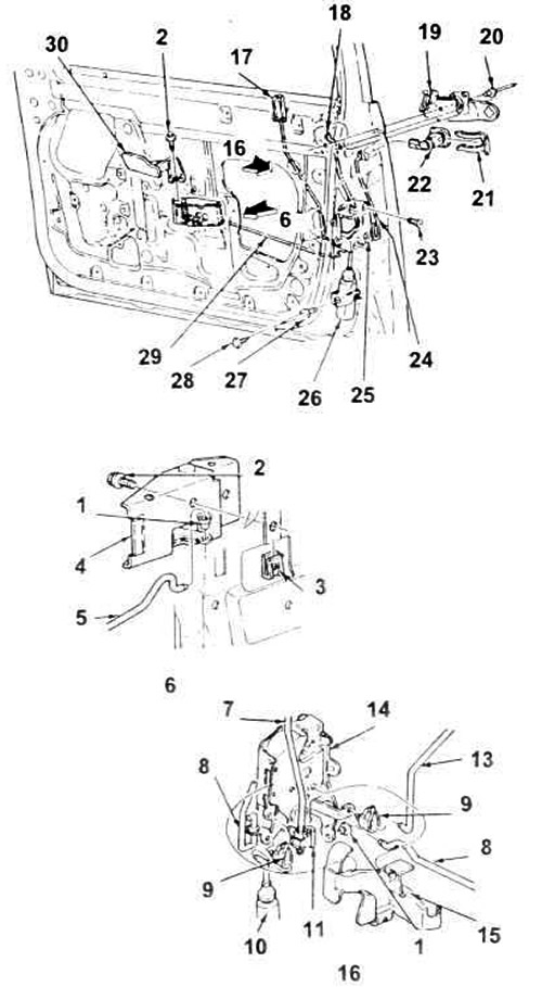
16.2, a. Typical parts of the front door lock drive.
1. Bushing.
2. Screw and washer.
3. Nut.
4. Inner handle assembly.
5. Inner handle pull.
6. View A.
7. External handle pull.
8. External lock cylinder rod.
9. Clamp.
10. Electric lock drive.
11. Retainer.
13. Internal lock button rod.
14. Lock body.
15. Shield.
16. View B.
17. Lock button.
18. The rod between the handle and the lock.
19. External door handle.
20. Fastening the outer handle.
21. Lock cylinder retainer.
22. Lock cylinder.
23. Screw.
24. Thrust between the lock and the lock cylinder.
25. Castle.
26. Electric locking drive.
27. Rivet.
28. Piston.
29. Traction.
30. Internal handle.
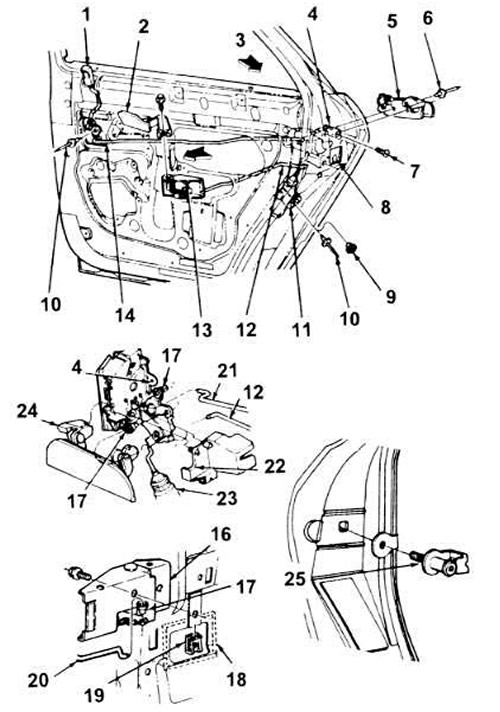
16.2, b. Typical parts of the rear door lock drive.
1. Lock button.
2. Internal handle.
3. View B.
4. Internal lock unit.
5. External handle.
6. Rivet (2 pieces).
7. Screw.
8. External door lock unit.
9. Washer.
10. Rivet.
11. Electric locking drive.
12. Inner handle pull.
13. External handle assembly.
14. Rocker and locking rod.
16. Inner handle assembly.
17. Bushing.
18. Inner handle seal.
19. Nut.
20. Traction.
21. Locking rod.
22. Shield.
23. Electric locking drive.
24. Handle assembly.
25. External lock latch.
3. Disconnect the button rod and the outer handle from the lock.
4. Unscrew the mounting screws and remove the lock.
5. Installation is carried out in reverse order.
(For details, please visit the website www.fordbook.ru)