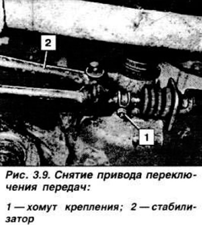
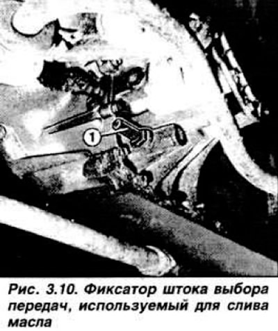
Remove stabilizer 2, installed between the gearshift drive and the gearbox. Hang the stabilizer and the drive rod to the steering gear housing. Carefully unscrew the gear selection rod retainer, remove the locking pin and spring. After removing the retainer, almost all the oil will flow out of the gearbox housing (Fig. 3.10).
Disconnect the ball joints of the lower suspension arms from the steering knuckles and move the arms to the side. Using a large screwdriver, remove the inner joints of the front drive shafts from the axle gears, and install technological plastic mandrels or old joints in their place to hold the axle gears in place. Suspend the drive shafts to the body so that the bending angle of the inner joint does not exceed 20°, and that of the outer joint does not exceed 45°. Unscrew the four bolts securing the gearbox to the bracket and one nut securing the bracket itself. Unscrew the three bolts securing the gearbox to the rear bracket and one bolt securing the bracket (for a five-speed gearbox, move the stabilizer bar on the left side to the side).
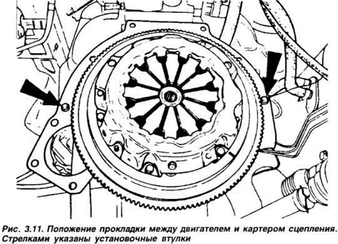
Loosen the two lower bolts securing the clutch housing to the engine, lower the engine so that the gearbox can be removed. Before installation, apply a thin layer of grease to the splined end of the input shaft and to the outer surface of the guide sleeve of the clutch release bearing coupling. Make sure that the gasket between the engine and the clutch housing is correctly positioned on the mounting sleeves (Fig. 3.11), insert the end of the input shaft of the gearbox into the splined hole of the driven disk and move the gearbox forward until the clutch housing touches the rear mating surface of the engine and tighten the bolts securing the gearbox to the engine with a torque of 3.5-4.5 kgf·m and to the powertrain suspension bracket with a torque of 8.0-10.0 kgf·m.
Loosely tighten the gearbox rear support bracket mounting bolt. For a five-speed gearbox, install the stabilizer bar on the left side. Then, for all gearboxes, tighten the rear support bolts, install the retainer, return spring, and gear shift drive rod. Replace the retaining rings on the inner joints of the wheel drive shafts with new ones, remove the process mandrels, and install the shafts in the gearbox, pressing hard on the shafts so that the retaining rings fit into the grooves of the axle gears. Replace the lower suspension arms. Install the washer between the gearbox housing and stabilizer 2 (Fig. 3.9) and tighten the bolt to a torque of 1.7–2.0 kgf·m.
Four-speed gearbox
Using a 3.5 mm diameter pin (Fig. 3.12), lock the gear shift lever in the cup of its ball joint, attach the spring to the drive rod and to the body side member.
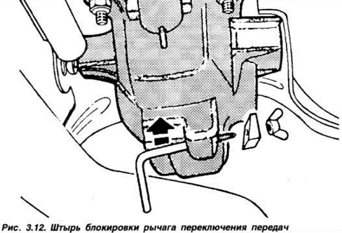
To evenly distribute the gaps, push the gear selector shaft into the IV gear position and turn it clockwise until it stops.
Five-speed gearbox
After installing the stabilizer, engage reverse gear. To do this, set the gear selection shaft to neutral, then use the pin to turn it clockwise until it stops and push it all the way into the gearbox housing.
For all gearboxes
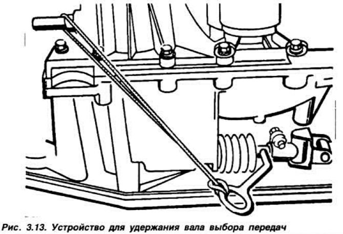
To hold the gear selector shaft in this position, use the device shown in Fig. 3.13.
Connect the drive rod to the shaft, making sure that there is no grease on the coupling coupling. Tighten the bolt of the coupling coupling of the drive rod on the rod to a torque of 1.7-2.0 kgf·m and remove the pin. Replace the clutch housing cover and lower the car to the floor. Remove the brace for lifting the engine. Tighten the upper gearbox housing mounting bolts. Connect the clutch drive cable and install the speedometer drive. Fill the gearbox with oil. Connect the hose to the thermostat housing and the heater and connect the battery. Insert the crankcase ventilation hose into the recess in the side member.