Note: Read the description of the entire procedure, and especially the instructions for lifting equipment. Depending on your funds, you can first remove the power block, and then undock the engine from the transmission at the workbench (chapter 2).
Withdrawal
1. Disconnect the negative battery cable (chapter 5A). You can remove the battery for better access.
2. If necessary, remove the hood (chapter 11).
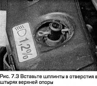
3. Fix the radiator in working position by inserting cotter pins into the holes in the pins of the upper support (see fig. 7.3). This is to hold the radiator when removing the subframe.
4. Remove the air flow meter and intake duct (chapter 4A). On V-6 models, remove the coolant pump pulley cover.
5. Remove the air cleaner assembly (chapter 4A).
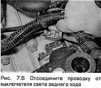
6. Disconnect the wiring from the reverse light switch on the transmission (see fig. 7.6).
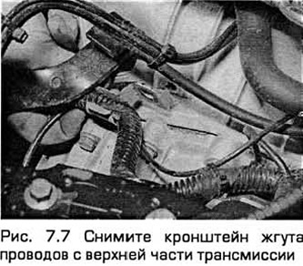
7. Remove the bolt and remove the harness bracket from the top of the transmission (see fig. 7.7).
8. Disconnect the ground wire connecting the transmission to the body. On V-6 models, disconnect the accelerator cables and cruise control devices. On the same models, disconnect the wiring from the steering hydraulic pressure sensor. Then release the piping for this hydraulic system from the clip on the bracket on the right side of the engine and move the piping to the side.
9. Disconnect the clutch cable or pipe from the transmission (chapter 6).
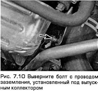
10. Turn out three top bolts of fastening of transmission to the engine. Turn out also the bolt with a mass wire installed under the exhaust manifold (see fig. 7.10).
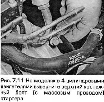
11. On models with 4-cylinder engines, unscrew the upper mounting bolt of the starter, taking into account that a ground wire is installed on it (see fig. 7.11). On models with V-shaped 6-cylinder engines, remove the starter (chapter 5A).
12. Apply the parking brake, raise the front end and place it on supports. Remove the front wheels.
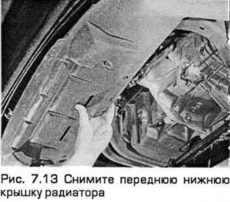
13. Remove the front bottom cover from the bottom of the radiator. To do this, release it from the clamps and unscrew the fixing bolts (see fig. 7.13).
14. Remove the wheel arch locker from the right side of the car (chapter 11).
15. Turn out bolts and remove a cover of a drive of auxiliary units.
16. Disconnect the anti-roll bar link from the suspension strut. To do this, working alternately on each side of the car, unscrew the nut of each link. Note that the link stud has a brake hose bracket attached to it.
17. Pull out cotter pins, and then turn away nuts of fastening of a limit switch of each cross steering draft to a rotary fist. Release the ball joints from the steering knuckles with a ball joint puller.
18. Working alternately on each side of the vehicle and taking into account which side the front suspension lower arm ball joint clamp bolt is inserted, remove the bolt. Take it off your fist. Press the ball joint away from the steering knuckle. If this is difficult to do, open the joint with a power screwdriver or pry bar. Do not damage the ball joint seal.
19. Disconnect the cooling fan electrical connector located on the subframe behind the radiator. Detach the connector plug from the bracket.
20. Disconnect the oxygen sensor wiring connector. Then unfasten the wiring harness from the rear engine mount.
21. Disconnect a vacuum hose from the filter of system of afterburning of fuel.
22. Remove the entire exhaust system (chapter 4).
Models manufactured before 1997 with lever-operated gear shifting
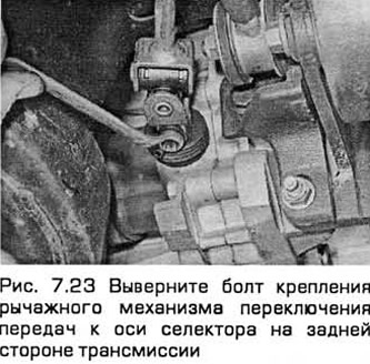
23. Turn out a bolt of fastening of the lever mechanism of a gear change to an axis of the selector on the back party of transmission (see fig. 7.23).
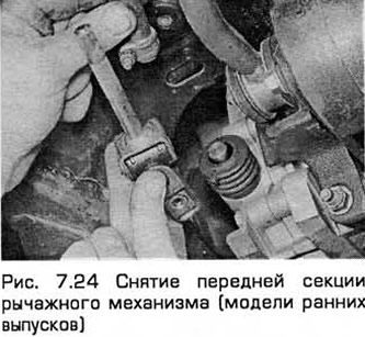
24. Mark the position of the rear section of the linkage relative to its front section. Loosen the clamp bolt. Disconnect the linkage from the selector shaft at the rear of the transmission. Separate the front section from the back (see fig. 7.24).
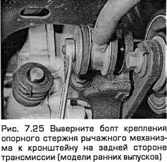
25. Remove the bolt and disconnect the linkage support rod from the bracket on the back of the transmission, (see fig. 7.25).
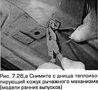
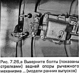
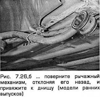
26. Remove the heat-insulating casing of the lever mechanism from the bottom. To do this, unscrew the nuts. Remove the bolts of the rear linkage support, tilt the mechanism back and tie it to the body (see fig. 7.26, a-c).
Models since 1997 with cable shift
27. Disconnect both cables from the transmission (paragraph 3).
All models
28. On models with an air conditioning system, remove the bolts securing the evaporator to the subframe and tie the evaporator.
29. Turn out bolts of fastening of the steering mechanism to a stretcher. It is difficult to get to them with a normal key. It is advisable to use a Ford crank adapter (chapter 10).
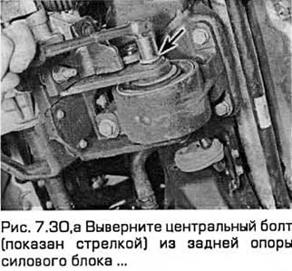
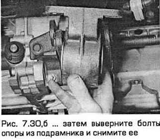
30. Unscrew the central bolt from the rear support of the power block (roll limiter). Then unscrew the support bolts from the subframe (see fig. 7.30, a, b).
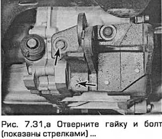
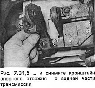
31. On lever driven models, remove the nut and bolt and remove the support rod bracket from the rear of the transmission (see fig. 7.31, a, b).
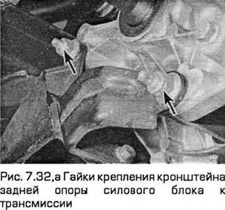
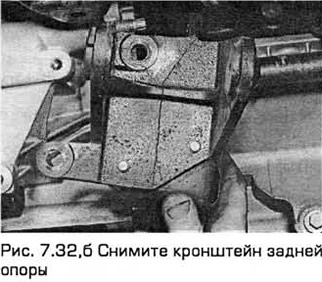
32. Turn away nuts and bolts and remove an arm of a back support of the power block from transmission (see fig. 7.32, a, b).
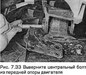
33. Turn out the central bolt from a forward support of the engine. Disconnect the filter of the afterburning system from the bracket located on the support (see fig. 7.33).
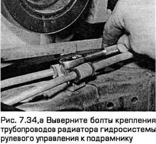
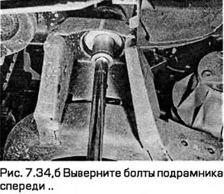
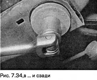
34. Together with an assistant, supporting the subframe, unscrew the bolts securing the steering hydraulic radiator pipes to the subframe. Then unscrew the subframe bolts and lower it to the ground (see fig. 7.34, a-c).
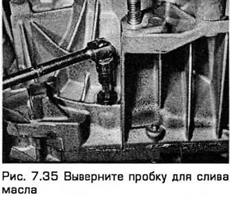
35. Place a container under the transmission. Then remove the oil drain plug (see fig. 7.35). Finally install and tighten the plug.
36. Turn out bolts of fastening of the central bearing of the right leading shaft to the block of cylinders. Remove the heat shield. Then pull the right strut so that the countershaft comes out of the transmission differential. Get ready to clean up oil leaks.
37. Support the right drive shaft on a support so that the inner joint does not rotate more than 18° (otherwise it may be damaged).
38. Insert a pry bar between the left driveshaft inner pivot and transmission housing (placing a thin piece of wood between the case and the mount). Then press the hinge away from the differential. If necessary, tap the mount with the palm of your hand. Be careful not to damage adjacent components and get ready to clean up oil spills. After the right drive shaft has been removed, the left drive shaft can be released by inserting a forked end drift from the right side. Be careful not to damage the differential gears.
39. Support the left drive shaft on a support so that the inner joint does not rotate more than 18° (otherwise it may be damaged).
40. Disconnect the engine speed sensor wiring connector.
41. On early models, remove the cable nut and disconnect the speedometer cable from the top of the vehicle speed sensor. While loosening the nut, hold the sensor with a wrench.
42. If necessary, the vehicle can be lowered to the ground at this stage to connect the lift to the engine. If the engine is suspended from a rod supported by the engine compartment, the vehicle may remain in the raised position.
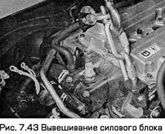
43. Attach the hoist by attaching the hook to the engine lifting lugs diagonally and hang out the power unit (see fig. 7.43).
44. Turn away nuts of an arm of the right support of the engine. Please note that if this support is hydraulic (chapter 2A paragraph 22), then it should not deviate from the vertical by more than 5°.
45. Turn away nuts and remove the left support of the power block from transmission.
46. On models with an air conditioning system, lower the engine until the compressor is below the right cross member.
47. On models without an air conditioning system, lower the transmission until it is opposite the opening located on the left side of the engine compartment.
48. Support the transmission with a jack. Secure it to the jack with chains or with a suitable cradle.
49. On models with 4-cylinder engines, remove the remaining starter bolts.
50. Turn out the bottom bolts of fastening of transmission to the engine. Turn out also bolts of fastening of the bottom cover to transmission.
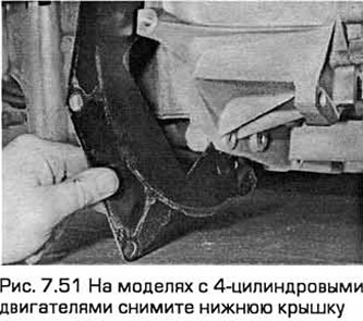
51. Together with an assistant, separate the transmission from the engine, trying not to warp it and so that the clutch friction disc does not take the weight of the transmission. After removing the transmission, remove the bottom cover installed between the transmission and the engine (see fig. 7.51). Lower the transmission to the ground.
52. Now you can inspect the clutch components (chapter 6) and replace if necessary.
Installation
53. Install clutch components (chapter 6), if they were removed.
54. Raise the transmission, fixed on the jack, to the working position, and then carefully dock it with the rear of the engine so that the input shaft enters the splines of the clutch friction disc. Do not apply excessive force. If the input shaft is difficult to enter, then rotate the transmission to a horizontal position and / or rotate the transmission in a horizontal plane. If this does not help, check if the clutch friction disc is correctly centered (chapter 6).
55. Insert the lower transmission-to-engine bolts and lightly tighten them.
56. On models with 4-cylinder engines, insert and tighten the starter bolts, taking into account that one of them is attached to the ground wire. On models with V-shaped 6-cylinder engines, install the starter (chapter 5A).
57. Raise the transmission to its working position.
58. Install the left power block support and tighten its nuts.
59. Establish an arm of the right support of the engine and tighten its nuts.
60. Raise the front and place it on supports if it was lowered to the ground.
61. Install the speedometer cable to the vehicle speed sensor and tighten the cable nut.
62. Connect the wiring to the speed sensor.
63. Insert the left drive shaft into the transmission so that the internal elastic ring of its fixation snaps into place.
64. Install the right drive shaft and intermediate shaft and tighten the bolts.
65. Install and align the subframe (chapter 2B paragraph 4). Tighten the bolts to the required torque.
66. Install the afterburner filter. Tighten the center bolt of the front engine mount.
67. Install the rear engine mount bracket and tighten the bolts.
68. Install the transmission support rod and bracket and tighten the bolts and nut.
69. Install the rear engine mount on the subframe and tighten the bolts.
70. Install the steering gear on the subframe and tighten the bolts.
71. On models with an air conditioning system, install the evaporator on the subframe and tighten the bolts.
72. Install shift mechanism and heat shield (paragraph 3).
73. Install the transmission shifter support rod to the rear of the transmission and tighten the bolt. Adjust the mechanism if necessary (paragraph 2).
74. Install the exhaust system (chapter 4).
75. Attach a vacuum hose to the afterburner filter.
76. Connect the oxygen sensor wiring.
77. Connect and fix the electrical connector of the cooling fan.
78. Install the ball joint of each lower front suspension arm on the steering knuckle (chapter 10).
79. Install the trailer of each tie rod on the steering knuckle (chapter 10).
80. Establish connecting links of the stabilizer of cross-section stability on racks of a suspension bracket and tighten nuts.
81. Install the accessory drive cover and wheel arch locker.
82. Install the lower front cover under the radiator.
83. Install the wheels and lower the car to the ground.
84. Insert the upper transmission-to-engine bolts.
85. Attach the clutch cable or pipe (chapter 6). On V-6 models, connect the steering hydraulic line. Restore the pipeline mounting on the bracket on the right side of the engine. The ground wire must be secured to one of the nuts on this bracket. Connect the harness to the steering hydraulic pressure sensor.
86. Connect the ground wire to the transmission and body.
87. Install the wiring harness bracket to the top of the transmission.
88. Connect the wiring to the reversing light switch.
89. Fully tighten all transmission mounting bolts.
90. Install air cleaner assembly, air flow meter and intake duct (chapter 4A).
91. Pull out the cotter pins that secure the radiator.
92. Install the hood if it was removed.
93. Install the battery, if it was removed, and connect its wires.
94. Fill the transmission with oil and check its level (Chapter 1).
95. Finally, check and make sure you have connected everything. necessary and the bolts are fully tightened.
96. Check the car on a trip by checking the operation of the transmission. Then check for oil leaks.
Visitor comments