Gear shift lever mechanism (models produced before 1997)
Removal
1. Remove the central console (Chapter 11). See Fig. 3.1.
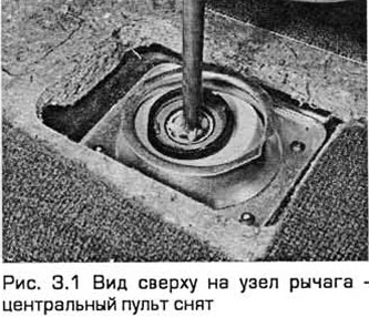
2. Apply the parking brake, raise the front end and place it on stands. Set the gearshift lever to neutral.
3. Working underneath the vehicle, remove the bolt and disconnect the linkage from the selector shaft at the rear of the transmission.
4. Mark the position of the rear section of the linkage relative to its front section. Loosen the clamp bolt and remove the front section.
5. Remove the bolt securing the linkage support rod to the bracket on the rear of the transmission.
6. Remove the heat-insulating casing. While supporting the linkage assembly, unscrew the nuts from the rear support bracket and lower the assembly (see Fig. 3.6).
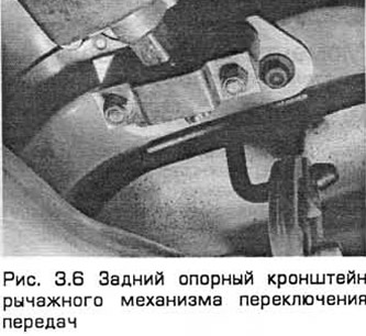
7. Remove the rubber insulator from the back of the unit.
8. Check the rubber insulator and rubber support of the stabilizer bar for wear and damage and replace them if necessary.
Installation
9. Installation - in the reverse order of removal. Adjust the lever mechanism (paragraph 2).
Cable shift mechanism (models produced since 1997)
Removal
10. Disconnect the negative battery cable (chapter 5A).
11. Apply the parking brake. Raise the front end and place it on stands. Remove both front wheels.
12. Remove the shield from under the engine and the left wheel arch liner.
13. Remove the cables from the brackets on the transmission by turning the spring-loaded bushings with notches (in different directions) counterclockwise. Pull out the stoppers and release the cables from the transmission levers, remembering their position. Pull the cables down from the engine compartment (see Fig. 3.13, a, b).
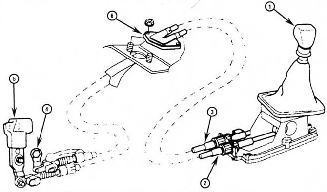 Fig.3.13.a. Components of the cable gear shift mechanism (models produced since 1997)
1. Gear shift lever
2. Gear shift cable
3. Gear selection cable
4. Gear selector lever on the transmission
5. Gear shift lever on the transmission
6. Adapter
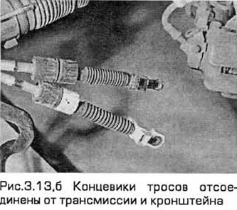
14. Make sure that the transmission levers are installed vertically (in neutral position).
15. Remove the air cleaner (chapter 4A).
16. Remove the shift knob. On early models, the knob is pressed into the shift lever. On later models, it is threaded.
17. Unfasten and remove the cover from the lever.
18. Remove the central console (Chapter 11).
19. Pull the cable ends out of the protrusions on the gearshift lever. Then disconnect the cable couplings from the bracket by turning the knurled bushings (in different directions) counterclockwise.
20. Remove the bolt and remove the air duct from the center groove.
21. If necessary, cut the mat and fold it away from the cable adapter location.
22. Unscrew the nuts and remove the adapter from the floor. Then pull the cables through the partition into the passenger compartment.
23. To remove the shift lever assembly, release the elastic ring on the end of the bearing rod and remove the spacer washer, spring and lever (see Fig. 3.23).
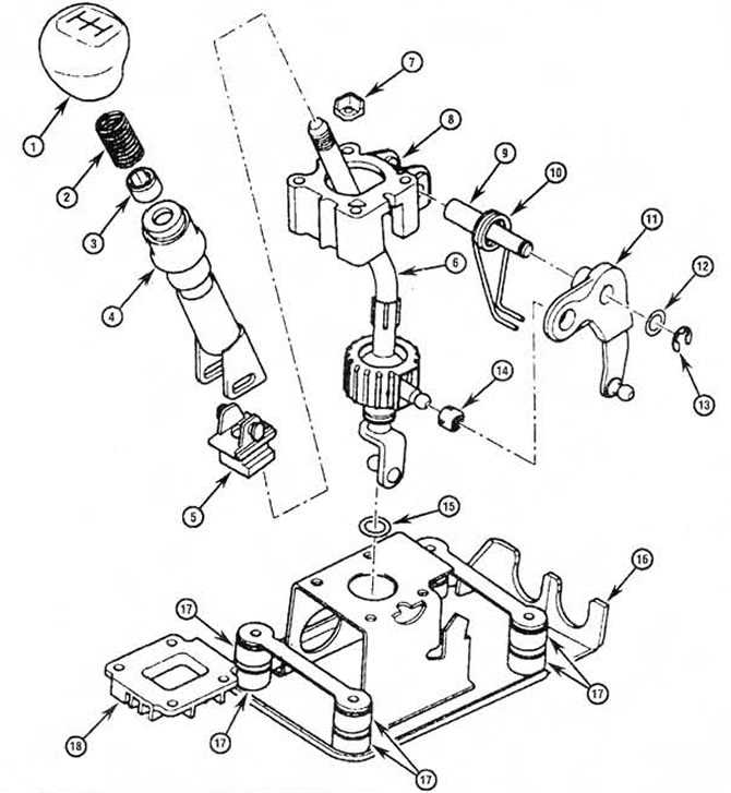 Fig.3.23. Components of the gear shift lever.
1. Handle
2. Spring
3. Damping bushing
4. Reverse gear switch
5. Locking sleeve
6. Gear shift lever
7. Reverse gear engagement element
8. Bearing housing
9. Bearing rod
10. Spring
11. Lever
12. Distance washer
13. Elastic ring
14. Bearing insert
15. O-ring of circular section
16. Body bracket
17. Damping rings
18. Support plate
24. Remove the bolts and bearing housing and support plate, reverse gear engagement element and bearing shell.
25. If necessary, bend back the stoppers and remove the brackets and studs.
Installation
26. Installation - in the reverse order of removal. Adjust the cables (paragraph 2).
The original article is posted at (www.fordbook.ru)
заехал в гараж,всё в норме.Через 2 дня сел в машину и обнаружил,что рычаг переключения передач заклинил и не шевелится вообще.Затем завёл на вижатом сцеплении и потихоньку разработал,СТАЛО ВСЁ В НОРМЕ.Вероятно всё от "обилия" смазки или в коробке или к механизме переключения передач,так и неразобрался.