Contents: 4-cylinder engines (models produced… ↳ Removal ↳ Separation ↳ Installation ↳ 4-cylinder engines (models produced… ↳ Removal ↳ Separation ↳ Installation ↳
Warning: Gasoline is highly flammable. Use extreme caution when working around the fuel system. Work in a well-ventilated area - open all windows and doors to create an exhaust hood. Do not smoke or allow open flames or unshielded incandescent lamps near the work area. Note that fuel used in household appliances (heaters, boilers, dehumidifiers) is also dangerous. Keep this in mind when working near such equipment. Always have a fire extinguisher suitable for extinguishing burning petroleum products near the work area, and read the instructions for its use before starting work. If fuel comes into contact with your skin, wash it off immediately with soap and water. Keep in mind that fuel vapors are just as dangerous as liquid fuel.
Note: Before performing this procedure, read this entire paragraph as well as the previous one. The engine and transmission must be removed as a unit by lowering it to the ground and removing it from under the vehicle, and then the engine and transmission must be separated.
4-cylinder engines (models produced before 05.1998)
Removal
1. Place the car on a firm horizontal surface, apply the parking brake. Loosen the front wheel nuts.
2. Eliminate residual pressure in the fuel system (Chapter 4).
3. Disconnect the negative battery cable (Chapter 5, paragraph 1). The battery can be removed for better access (Chapter 5).
4. Cover the fenders and front crossmember of the engine compartment, then remove the hood (Chapter 11).
5. Whenever you disconnect vacuum hoses, coolant hoses, ventilation hoses, electrical connectors, ground wires, fuel lines, as required by the following procedure, mark the disconnected parts with tags so that you can secure them in place when installing.
6. Disconnect the two electrical wiring connectors, disconnect the vacuum hose (if equipped), disconnect the crankcase ventilation hose from the cylinder head cover. Remove the air cleaner assembly together with the air flow meter, resonator and pre-chamber (Chapter 4).
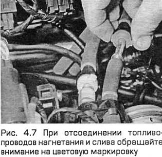
7. Equalize the pressure in the fuel tank with the atmospheric pressure by removing its filler cap. Then detach the fuel supply and outlet lines secured to the chassis (Chapter 4A) and plug or cover all the resulting openings (see Fig. 4.7).
8. Disconnect the accelerator cable from the throttle linkage (Chapter 4A). Also disconnect the cruise control cable (if equipped) (Chapter 12). Secure the cable(s) away from the engine/transmission.
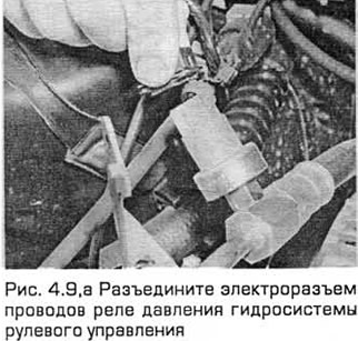
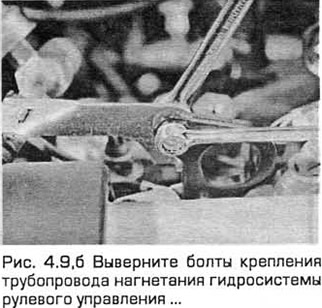
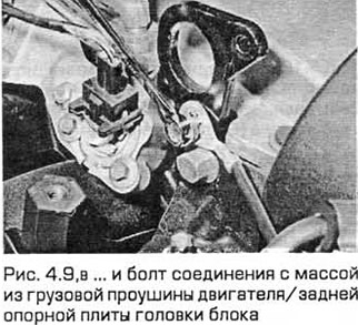
9. Release the wire retainer and disconnect the electrical connector of the power steering pressure relay wires. Remove the power steering pressure pipe mounting bolts and the ground connection bolt from the engine lifting eye/rear support plate of the cylinder head (see Fig. 4.9,a-c).
10. When marking, disconnect the vacuum hoses in the following order:
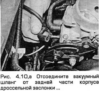
- a) One - from the rear of the throttle body. (Disconnect only one hose. The second hose, which goes to the fuel pressure regulator, does not need to be disconnected.) (See Fig. 4.10,a).
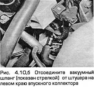
- b) One - from the fitting on the left edge of the intake manifold (see Fig. 4.10.6).
- c) Brake booster vacuum hose (Chapter 9).
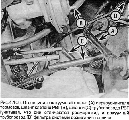
- d) Disconnect all vacuum hoses from the EGR system components - one from the EGR valve and two from the EGR line. Note that the last two hoses have different sizes of nozzles and therefore cannot be mixed up.
- d) The vacuum line coming from the fuel afterburning system filter housing and passing over the transmission must be disconnected. To do this, pull the plastic pipe out of the rubber hose located under the fuel afterburning system electromagnetic valve installed on the engine compartment bulkhead (see Fig. 4.10, c).
- e) Secure all these hoses so that they are not damaged when removing the power unit.
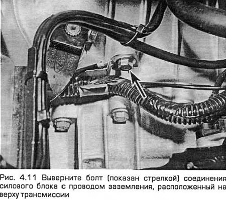
11. Remove the bolt connecting the power unit to the ground wire. This bolt is located on top of the transmission (see Fig. 4.11). Disconnect the speedometer drive cable (Chapter 12) and secure it away from the power unit.
12. On models with manual transmission, disconnect the clutch cable (Chapter 6). On models with automatic transmission, disconnect the selector cable (Chapter 7B) and secure it away from the power unit.
13. Labeling all components to be removed, disconnect the engine wiring harness from the body as follows:
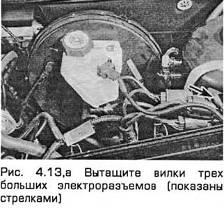
- a) Starting from the left side of the engine compartment, remove the plugs from the three large electrical connectors attached to the suspension support. (Note that some connectors are secured with wire clips (see Fig. 4.13.a).
- b) Disconnect and/or release the wiring from the battery to the starter by disconnecting one electrical connector.
- c) Disconnect the wiring harness connectors to disconnect the engine speed sensor, oxygen sensor, and (if equipped) oil level sensor wiring. Release the connectors from the retainers where necessary to free the wiring.
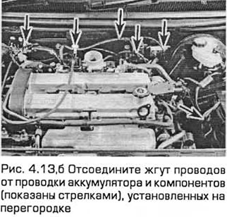
- d) Disconnect the wiring harness from the clips and disconnect the various components (by disconnecting the connectors) mounted on the bulkhead. Work in the engine compartment from left to right along the entire length of the harness (see Fig. 4.13.6).
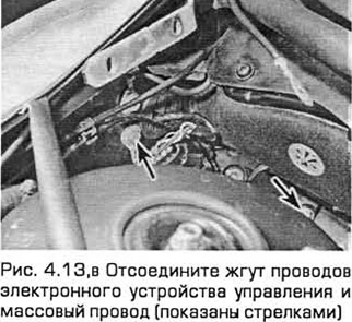
- d) Carefully pull the power steering fluid reservoir upwards from its clamps securing the reservoir to the suspension support. Then unscrew the mounting bolt of the electronic control unit electrical connector and pull out the plug of this connector (see Fig. 4.13, c).
- e) Remove the ground wire bolt from the right wing inner panel. Release the engine wiring harness and install the power steering fluid reservoir.
- g) Secure the engine wiring harness so as not to damage it when removing the power unit from the vehicle.
14. Remove the bolts from both parts of the exhaust manifold heat-insulating casing. Disconnect the coolant hose to remove the upper part of the casing.
15. Remove the accessory drive belt (chapter 1).
16. Remove the power steering pump bolts (Chapter 10). Secure it as far away from the power unit as possible without disconnecting the hoses.
17. Raise the car and place it on stands. Then remove the front wheels. Drain the cooling system and (if you are disassembling the engine) drain the engine oil and remove the oil filter (chapter 1). Also drain the transmission fluid (Chapter 7).
18. Remove the lower part of the exhaust manifold heat insulating boot.
19. Loosen the nuts to disconnect the exhaust downpipe from the manifold. Then remove the entire system from its rubber mounts and pull it out from under the vehicle (Chapter 4A).
20. On manual transmission models, mark the position of the shift linkage and transmission support rods on the rear of the transmission. Loosen the mounting nuts and remove the shift linkage heat shield from the underbody. Loosen the bolt securing the rear end of the shift linkage to the underbody, swing the shift linkage back and tie it to the underbody (Chapter 7A).
21. Disconnect both anti-roll bar connecting links from their respective suspension struts and the tie rod ends from the steering knuckles. Note the brake hose bracket secured to the stud of each connecting link. Loosen the clamp bolt securing the ball joint of each lower front suspension arm to the steering knuckle (Chapter 10). Make sure that both ball joints can be released from the steering knuckles if required and leave them in place, securing them with clamp bolts if necessary.
22. On models with air conditioning, remove the battery/water separator bolts from the subframe. Secure this unit as far away from the power unit as possible without disconnecting the system hoses.
Warning: Do not disconnect the refrigerant hoses.
23. Remove the steering gear bolts from the subframe. If the bolts are not accessible from above, you will need the Ford tool to access them from underneath the car (Chapter 10).
24. Remove the two bolts securing the hydraulic steering system line to the right side of the subframe.
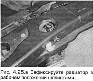
25. Secure the radiator in its working position. To do this, insert cotter pins through the holes in the rear part of the front crossmember of the engine compartment into the elements of the upper radiator supports. Unscrew the bolts of the radiator support brackets from the subframe. Note that they differ in shape, like mirror images, and are marked for the purpose of correct installation (see Fig. 4.25, a, b). Assemble the rubber elements of the lower supports, taking into account which side they are installed on, and fold them for storage.
26. Remove the rear powertrain mount bolts from the subframe. On automatic transmission models, there may be a separate damper installed under the subframe, the bolts of which must be removed to access the mount fasteners. On manual transmission models, also remove the center mount bolt and remove the mount bracket bolts from the transmission.
27. Unscrew the central bolt of the front support of the power unit and unscrew the support bolts from the subframe, taking into account the position of the wiring connector bracket.
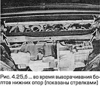
28. Mark the subframe and underbody with white paint or something similar (but do not scratch the surface) for proper installation. Remove the four support bolts from the subframe (note that they have different sized washers, see Fig. 4.47A) and release the subframe so that it hangs on the ball joints of the lower control arms. Disconnect the ball joints (one at a time) from the steering knuckle assemblies (Chapter 10) and lower the subframe to the ground. Pull it out from under the car.
29. Marking all disconnected components (see item 5) and preventing coolant leaks, disconnect the cooling system hoses and lines as follows (for details, see Chapter 3):
- a) Remove the upper radiator hose.
- b) Remove the hose (heater) going from the thermostat to the fitting located on the bulkhead of the engine compartment.
- c) Disconnect the hose from the thermostat that goes to the reserve tank. Secure this hose away from the work area.
- d) Disconnect the hose/pipe from the thermostat that goes to the lower radiator hose.
- d) Disconnect the lower radiator hose from the radiator nipple, from the heater coolant pipe and from the nipple of the cooling system pump. Secure this hose away from the work area.
- e) Unscrew the bolts of the coolant (heater) pipe from the pan. Disconnect from the pipe/hose (along its route to the fitting located on the bulkhead of the engine compartment), the hoses from the fittings of the oil radiator (if available), and then remove the coolant pipe.
- g) On models without air conditioning, secure the radiator by pushing it as far forward as possible from its operating position. On models with air conditioning, remove the radiator assembly (Chapter 3).
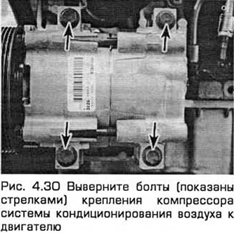
30. On models with air conditioning, disconnect the compressor wiring harness electrical connector and remove the compressor bolts from the engine (see Fig. 4.30). Secure the compressor as far away from the power unit as possible without disconnecting the system hoses.
Warning: Do not disconnect the refrigerant hoses.
31. On models with manual transmission, disconnect the drive shafts from the transmission as follows (see Chapter 8 for details):
- a) Unscrew the nuts securing the right drive shaft support bearing and remove the heat-insulating shield.
- b) Pull the right drive shaft out of the transmission. Be prepared to clean up any leaks.
- c) Secure the drive shaft away from the power unit. Remember that the unit will need to be lowered out of the vehicle and note that the inner joint cannot be turned more than 18°.
- d) Remove the left drive shaft from the transmission. Be prepared to clean up any leaks. Secure the shaft away from the transmission and ensure that the inner joint does not rotate more than 18°.
32. On models with automatic transmission, follow these instructions (see Chapter 7B and 8 if necessary):
- a) Remove the center bolt, then remove the rear powertrain mount bracket bolts from the transmission.
- b) Disconnect the transmission cooler line from the rear of the transmission and secure it away from the transmission.
- c) Remove the left drive shaft from the transmission. Be prepared to clean up any leaks.
- d) Secure the drive shaft away from the power unit. Remember that the unit will need to be lowered out of the vehicle and note that the inner joint cannot be turned more than 18°.
- a) Unscrew the nuts securing the right drive shaft support bearing and remove the heat-insulating shield.
- e) Pull the right drive shaft out of the transmission. Be prepared to clean up any leaks. Secure the shaft away from the transmission and ensure that the inner joint does not rotate more than 18°.
- g) Disconnect the transmission cooler line from the front of the transmission and secure the line away from the transmission.
33. The power unit now rests only on the left and right supports, along with all the components that normally connect it to other vehicle systems and that are now disconnected or removed and secured away from the power unit. Check again to make sure everything is done correctly. Then make sure the body is supported securely enough to perform the operation of removing the power unit from underneath.
34. Hang the power unit on the lugs located on the cylinder head. Unscrew the six nuts securing the right support bracket, and then the three nuts securing the left support bracket.
Warning: If the vehicle or power unit is supported only by a jack or other lifting mechanism, do not work under the power unit or vehicle!
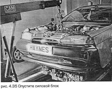
35. Lower the power unit to the ground and pull it out from under the vehicle (see Fig. 4.35).
Separation
36. Separate the transmission from the engine, following the instructions in Chapter 7.
37. After removing the power unit, check its supports and replace them if damaged or worn. Also check the condition of all coolant hoses, as well as vacuum hoses and lines (chapter 1). All components that are normally hidden can now be carefully examined and, if faulty, replaced. On models with manual transmission, it makes sense to disassemble the clutch components (Chapter 6). When performing a major engine overhaul, it makes sense to replace the entire clutch assembly. Check the condition of any components (such as transmission seals) that were displaced during removal and replace any that are damaged or worn.
Installation
38. Installation - in the reverse order of removal, taking into account the following. Tighten all fasteners to the required torque. If in the Technical Requirements chapters 2A and 2B if the required tightening torque for any connection is not specified, please refer to the Technical Requirements in the relevant chapter of this book.
39. In addition to the instructions in item 37, always replace any elastic rings and self-locking nuts removed during removal.
40. If the wiring is secured with ties that need to be untied when removed, then new ties need to be prepared for installation.
41. After completing the repair, install the transmission on the engine (Chapter 7).
42. Place the power unit under the vehicle, connect it to the lifting device and lift the unit to the installation site so that the right and left supports of the unit can be restored. Then tighten the nuts slightly. Keep the power unit supported by the lifting device. Its weight should not be transferred to the supports until all of them are correctly installed.
43. Install the drive shafts (Chapter 8) using new elastic rings and preventing the inner joints from turning more than the maximum angle. On models with manual transmission, this procedure is performed in the reverse order to that specified in paragraph 31. On models with automatic transmission, follow these instructions (Chapter 7B and 8):
- a) Install the left drive shaft.
- b) Attach the transmission cooler lines first to the rear and then to the front of the transmission, securing the clamps properly and tightening the couplings to the specified torque.
- c) Install the right drive shaft to the transmission. Install the heat shield. Tighten the support bearing nuts to the specified torque.
- d) Install the rear powertrain mount bracket to the transmission. Tighten the bolts to the specified torque, then install the mount and lightly tighten the center bolt.
44. On models with air conditioning, be sure to install the compressor. Tighten the bolts to the specified torque and connect its electrical connector.
45. Taking into account the observations and marks made during removal, install the cooling system hoses. Where they were disconnected or released from the clamps, do not forget to secure them at the appropriate time during the installation procedure. Install the radiator (if it was removed) and secure it with cotter pins in the operating position.
46. Position the subframe (one side at a time) and connect it via the lower control arm ball joints to the steering knuckles. Install the subframe bolts, making sure the washers are seated correctly, and lightly tighten the bolts.
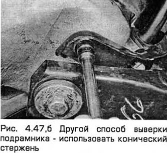
47. Now the subframe needs to be aligned on the body. For this purpose, there is a Ford 15-097 device, which is a pair of conical guides with places for fixing them on the subframe during its installation. But due to the fact that the working diameter of such devices is 20.4 mm, and the corresponding holes in the subframe and body are 21 and 22 mm, respectively, then when aligning the subframe, a significant gap is possible even when using regulated devices. If you do not have them, then the subframe can be aligned by eye, centering its hole relative to the body and using the marks made during removal. Another way to align the subframe is to use a conical rod (such as a clutch centering device) or even a high wrench head (of the appropriate size) (see Fig. 4.47, a, b).
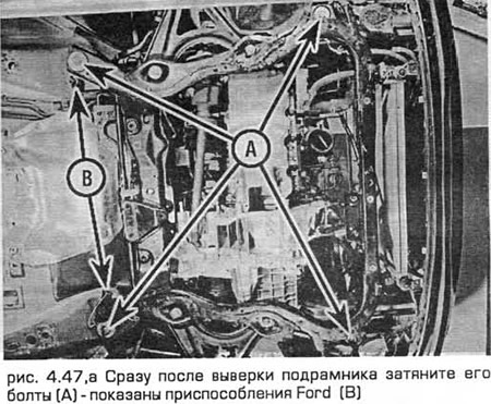
48. Immediately after aligning the subframe, tighten its bolts to the required torque, without over tightening it. After tightening the bolts, immediately recheck the subframe position.
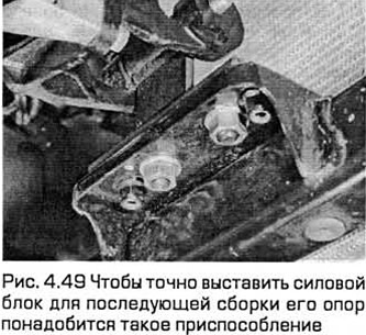
49. After the subframe has been aligned and securely fastened, it is necessary to accurately align the power unit for subsequent assembly of its supports. The Ford 21-172 device is intended for this purpose. This device is secured with bolts to the subframe instead of the front support of the power unit so that when the central support bolt is installed, it is held in the position: 60 mm above the upper surface of the subframe with a 20 mm offset back relative to the axes of the holes for the bolts for the subframe support. If you do not have such a device, then you need to make a copy of it to perform this operation (see Fig. 4.49).
50. Attach the fixture to the subframe in place of the front power unit support and lightly tighten the center bolt. Install the power unit supports in the following sequence:
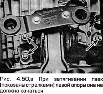
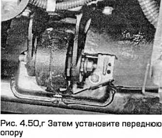
- a) Tighten the nuts of the left support to the required torque. When tightening them, the support should not swing (see Fig. 4.50,a).
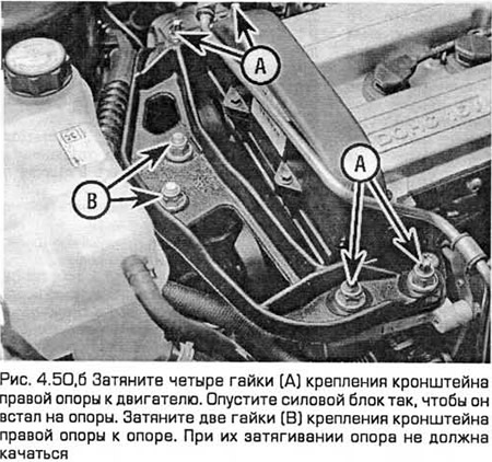
- b) Tighten the four nuts securing the right support bracket to the engine to the specified torque.
- c) Using a lifting mechanism, slowly lower the power unit until it rests on the supports.
- d) Tighten the two nuts securing the right support bracket to the support to the required torque. When tightening them, the support should not swing (see Fig. 4.50.6).
- d) Assemble the rear support of the power unit and tighten the fasteners to the required torque. Finally, tighten the central bolt.
- e) Install the steering gear to the subframe. If you use the Ford underbody tightening tool (Chapter 10), note that you will need a torque wrench that can tighten counterclockwise.
- g) Remove the special tool bolts from the front support. Then install the front support. Do not forget about the wiring connector bracket. Tighten the support bolts/nuts to the required torque first, and then the central bolt (see Fig. 4.50, c, d).

51. Install the lower rubber supports under the radiator with the appropriate side. Then install the radiator support brackets on the subframe (in the required position - according to the marks). Tighten the bolts to the required torque. Remove the cotter pins and secure the coolant hose connections (if necessary).
52. Install the air conditioning accumulator/water separator (if equipped) to the subframe.
53. Tighten the two power steering line mounting bolts located on the right side of the subframe.
54. Secure the ball joint of each lower control arm and each end of the tie rod to the appropriate steering knuckle, and both anti-roll bar connecting links to the appropriate suspension struts. Note the brake hose bracket secured to the stud of each link (Chapter 10).
55. On manual transmission models, move the linkage forward, tighten its rear fasteners, and then install the linkage heat shield. Connect the linkage (shift) to the transmission support rods and adjust the linkage using the marks made during removal (Chapter 7A).
56. Install the remaining components and fasteners in the reverse order of removal.
57. Top up the engine with coolant and oil, and the transmission with working fluid (chapter 1).
58. Start the engine and check that it runs reliably and that there are no leaks. Stop the engine and recheck the fluid levels.
59. Remember that if the front suspension subframe and steering gear have been removed and installed, it is necessary to check the wheel and steering angles at the first opportunity and make any necessary adjustments. This work is best left to specialists (dealers).
4-cylinder engines (models produced since 05.1998)
Note: This procedure is for manual transmission models. For automatic transmission models, the procedure is the same as for pre-05/1998 models.
Removal
60. Remove the battery. (Chapter 5A). Place the transmission in neutral (non-automatic transmission) or in position "P" (automatic transmission).
61. Remove the hood (Chapter 11).
62. Loosen the nuts of the upper supports of both front suspension struts one by one (loosening the nut approximately 5 turns at a time and holding the shock absorber rod with a wrench).
63. Apply the parking brake. Raise the front end and place it on supports. Remove both front wheels.
64. Remove the lower radiator cap. Drain the liquid from the cooling system.
65. Disconnect the wiring from the mass air flow meter and air temperature sensor.
66. Remove the air cleaner assembly (Chapter 4A), then remove the air intake duct chamber.
67. Disconnect the battery wiring (including the ground cable) from the battery tray.
68. In the right front corner of the engine compartment, unscrew the bolts of the wire connection box and move it to the side.
69. Unscrew the bolts and remove the battery tray, taking into account the position of the wires.
70. At the right rear corner of the engine compartment, remove the power steering fluid reservoir from its support and move it to the side. Remove the traction control module wire bracket bolts. Disconnect the two ground wires, then disconnect the traction control module wire connector.
71. Disconnect the ground wire from the engine cargo eye.
72. Disconnect the power steering pressure sensor wiring and release the wiring from its fasteners on the pipe.
73. In the engine compartment, on the left, disconnect the main engine wiring connector and also disconnect the ground wire. Release the wiring from the connections.
74. On models with a cruise control device, disconnect the cruise control device wiring from the throttle body. Then disconnect and remove the cruise control device cable. If necessary, refer to Chapter 12.
75. Disconnect and remove the accelerator cable from the throttle body. If necessary, refer to Chapter 4A.
76. Disconnect the vacuum hoses from the intake manifold and note their position.
77. Pull out the oil dipstick at the front of the engine. Then remove the bolts and the exhaust manifold heat shield. At the same time, remove the coolant pipe bracket.
78. Remove the coolant pipe and disconnect the hose from the coolant pipe and the cooling system pump.
79. Loosen the nuts securing the catalytic converter to the exhaust manifold and move the converter to the side.
80. On models with air conditioning, disconnect the compressor wiring on the right side of the engine.
81. Disconnect the wiring from the coolant temperature sensor near the engine lifting eye.
82. At the front of the engine, release the wiring from the front crossmember of the engine compartment.
83. Loosen the clamps and remove the hoses from the radiator and thermostat housing.
84. Disconnect the wiring from the electric fan.
85. Disconnect the hoses from the reserve tank in the right front corner of the engine compartment.
86. Remove the bolts and remove the upper belt drive cover located on the right side of the engine.
87. Place a container under the clutch hydraulic cylinder. Then release the clamp and disconnect the pipe (see Chapter 6 if necessary). Remove the pipe from the transmission and tie it to the side.
88. Disconnect the transmission ground wire.
89. Remove the bolts and remove the right front wheel hub.
90. Turn the accessory drive belt tensioner clockwise and remove the belt.
91. Release the quick-release coupling and disconnect the brake booster vacuum pipe from the intake manifold.
92. Locate the oxygen sensor wiring connector on the lower front side panel and disconnect it. Release the wiring from the connections.
93. Unscrew the bolts securing the flange of the front section of the exhaust system to the intermediate section. Remove the pipe from the rubber supports and remove it, as well as the gasket.
94. Remove the front lower arm ball joint clamp bolts and pull the lower arms out of the hubs. If necessary, see Chapter 10. Also remove the ABS wiring brackets from the suspension struts. Do not damage the rubber ball joint boots or the ABS sensor disc.
95. Remove both drive shafts (Chapter 8).
96. Remove the bolts and rear engine mount. Remove the mount bracket from the transmission.
97. Raise the transmission slightly with a jack, then remove the nuts and the center bolt of the front engine mount. Remove the mount.
98. Loosen the clamp bolt and remove the catalytic converter.
99. On models with air conditioning, disconnect the moisture separator, move it to the side and tie it down.
100. Loosen the clamps and disconnect the lower coolant hoses.
101. Loosen the clamp and disconnect the heater hose from the engine bulkhead.
102. On models with air conditioning, remove the compressor bolts, move it to the side without disconnecting the pipes, and tie it up.
103. Disconnect the shift linkage cable from the lever on the transmission. Turn the bracket counterclockwise to pre-tension, then remove the cable. Disconnect the other cable from the lever on the transmission. Turn the other bracket counterclockwise to pre-tension, then remove the cable. Press the adjuster inward to release it.
104. Eliminate residual pressure in the fuel system (Chapter 4A).
105. Disconnect the fuel supply and outlet hoses.
106. Remove the coolant reserve tank bolts and move the tank to the side. Disconnect the cruise control cable from the tank (if equipped).
107. Raise the power unit on the lift.
108. Mark the position of the right engine mount. Unscrew the mount nuts and loosen the bolts only two turns.
109. Mark the position of the left engine mount. Unscrew the mount nuts and bolts.
110. With the help of an assistant, carefully lift the power unit until the power steering pump is visible. Remove the pump bolts from the engine, move the pump to the side and tie it up.
111. Carefully remove the power unit from the engine compartment so as not to damage adjacent components.
Separation
112. Disconnect the wiring from the reverse gear indicator and engine speed sensor.
113. Disconnect the wiring from the starter main terminal and the solenoid terminal.
114. Remove the upper starter mounting bolts and the upper engine to transmission mounting bolts.
115. Remove the ground wire bolt from the transmission.
116. Remove the lower bolt and remove the starter. Remove the wiring.
117. Remove the remaining bolts securing the transmission to the engine.
118. Together with an assistant, separate the transmission from the engine without tilting it so that the input shaft comes out of the clutch assembly.
Installation
119. On models with automatic transmission, make sure that the torque converter is fully connected to the pump on the transmission output shaft. To do this, measure the distance from the flange to the journal on the torque converter with a ruler. It should be at least 12 mm. Move the transmission selector to the "D" position. Lubricate the journal with high-melting grease.
120. With the help of an assistant, connect the transmission to the engine so that the studs enter the holes in the faceplate. On models with an automatic transmission, align the torque converter with the faceplate.
121. Insert the bolts and tighten them sequentially to the required torque.
122. On models with automatic transmission, rotate the engine as required and tighten the torque converter nuts to the specified torque.
123. Perform the remaining procedures in the reverse order of removal, taking into account the following:
- a) Install the engine mounts in the same position as before removal.
- b) Tighten all nuts and bolts to the specified torque.
- c) Bleed the clutch hydraulic system (Chapter 6).
- d) Adjust the accelerator cable (Chapter 4A) and the cruise control cable (Chapter 15).
- d) Fill the cooling system (chapter 1).
This article was borrowed from the website fordbook.ru