Note: Before starting a repair, you need to make sure that you can obtain spare parts (see par. 1 of this chapter). If you do not have any of the spare parts, contact your dealer or engine rebuilder.
Note: This procedure can be done without removing the engine from the vehicle. However, it is difficult due to limited access and also requires the removal of various components. Therefore, it is recommended that you perform this work after removing the engine. You will need new gaskets and other spare parts, as well as a lifting mechanism. The following device can also be used to lift the power unit. It contains an adjustable support rod that must be inserted into the drain holes on both sides of the engine compartment, and a height-adjustable hook that hooks onto the eyes. The lifting capacity of this device (available at auto parts stores) should exceed the weight of the engine and transmission.
1. Remove the cylinder head(s) (Chapter 2A or 2B).
2. Remove the pan (Chapter 2A or 2B).
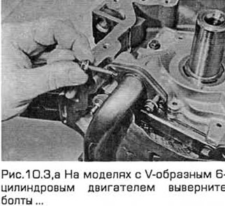
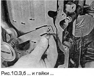
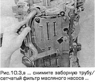
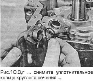
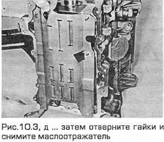
3. Loosen the screws securing the oil pump intake pipe/strainer to the pump and remove the O-ring. On models with a V-shaped 6-cylinder engine, loosen the nuts and remove the oil deflector from the crankcase (see Fig. 10.3, a-d). On models with a 4-cylinder engine manufactured from 05.1998, screw in the bolts and remove the lower crankcase frame.
4. On models with a 4-cylinder engine produced since 05.1998, the design of the connecting rods and their caps does not provide for their disassembly. The caps are separated from the connecting rods by breaking in a special way. Therefore, the mating surfaces for each connecting rod and its cap are unique and therefore these components cannot be confused (combined) with others.
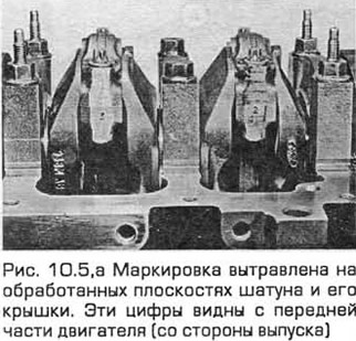
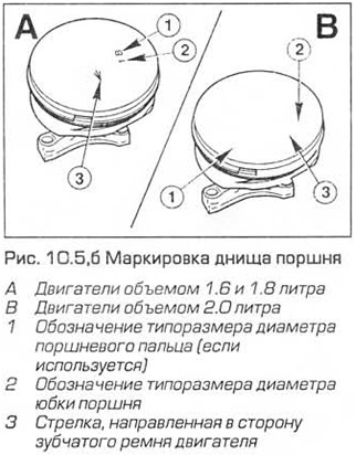
5. Temporarily install the crankshaft pulley so that the shaft can be turned. Note that the connecting rod and piston groups are marked according to the cylinder numbers. The markings are etched on the machined surface of the connecting rod and its cap. These numbers are visible from the front of the engine (from the exhaust side). In addition, an arrow is stamped on the bottom of each piston pointing towards the engine toothed belt/chains. If the marks are not visible, apply them before removing the components so that when installing, insert each connecting rod and piston group with the corresponding side into the corresponding cylinder and fix its cap with the corresponding side (see Fig. 10.5, a, b).
6. Run your fingernail along the top of the cylinder mirror to feel the step from the wear of the mirror by the piston ring (it is located approximately 0.5 cm from the end of the cylinder). If ridges have formed in the cylinder due to carbon deposits or wear, they must be removed with a special tool (see Fig. 10.6). Follow the instructions of the manufacturer of this tool.
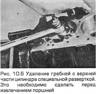
Warning: Failure to remove these ridges may result in damage to the piston rings when removing the pistons.
7. On models with a 4-cylinder engine produced from 05/1998, unscrew the bolts securing the lower crankcase to the cylinder block. Loosen the bolts gradually and evenly. Then separate the lower crankcase from the cylinder block.
8. Loosen the connecting rod bearing cap bolts (one-half turn at a time) until they can be removed by hand. Remove the cap and bearing shell from the connecting rod of the first cylinder. Be careful that the bearing shell does not fall out of the cap.
9. Remove the upper bearing shell and push the connecting rod and piston group through the top of the cylinder with a wooden hammer, tapping on the bearing bed of the connecting rod. If the unit comes out with difficulty, check again whether all the ridges have been removed from the cylinder.
10. Repeat this procedure on the remaining cylinders.
11. After removing the connecting rod and piston group, install the cover and liners, insert and tighten the bolts by hand. This is necessary to protect against accidental damage to the bearing beds. When installing, use new liners.
12. Do not attempt to separate the pistons from the connecting rods (see paragraph 12).