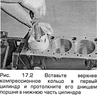
2. Insert the upper compression ring into the first cylinder and push it with the piston crown into the lower part of the cylinder. The ring will be located perpendicular to the cylinder walls (see Fig. 17.2). Move the ring to the area of its location corresponding to BDC.
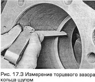
3. To measure the end gap of the rings, insert feeler gauges between the ends of the ring until you find a feeler gauge that matches the gap width (see Fig. 17.3). The feeler gauge should enter the gap with little resistance. Compare the measurement result with the Technical Requirements. If the gap is larger or smaller than specified, repeat the check to make sure that you are checking for serviceable rings. If you are not satisfied with the measurement result, you should have the cylinders checked by dealers, who can accurately determine which component is worn out and recommend the best way to rebuild the engine.
4. If the end gap in the ring is too small, it can be increased by filing the ends with a file. If the gap is large, this is normal as long as it does not exceed the specified limit. If the gap is larger than the specified limit, it is necessary to check the dimensions of all components, as well as new spare parts.
5. Repeat the procedure for all the tracks that you will install in the first cylinder, as well as in the remaining cylinders. Install the components in their places.
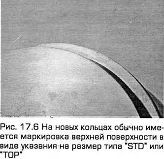
6. Install the piston rings as follows. If you are installing the old rings, do not forget about the marks made during removal so that the rings fall into place and fit into them with the appropriate side. New rings usually have a marking on the upper surface (in the form of an indication of the size such as "STO" or "TOP"). The rings should be installed with the marking facing up (see Fig. 17.6).
Note: Always follow the instructions supplied with the track kit. Do not interchange the top and second compression rings as they are usually of different cross-sections.
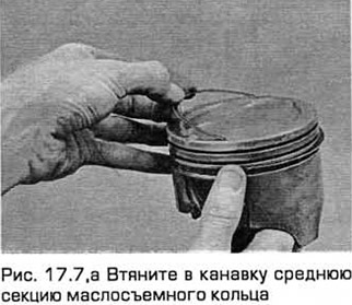
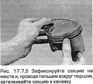
7. The oil control ring (the lowest on the piston) is usually installed first. It consists of three separate sections. Pull the middle section into the groove (see Fig. 17.7,a). If there is an anti-rotation element, make sure that it is inserted into the hole located in the groove of the ring. Then insert the lower section of the ring. Do not use a piston ring installer when installing the oil control ring sections, so as not to damage them, but proceed as follows. Place one end of the section in the groove between the middle section and the groove thorium, lock it in place and, running your finger around the piston, push the section into the groove (see Fig. 17.7,b). Install the upper section in the same way.
8. After installing the three sections of the oil scraper ring, make sure that the upper and lower sections rotate freely in the groove.
9. The second compression ring is installed after the oil scraper ring. And after it, you need to install the upper compression ring. Install these rings with the marking facing up and do not mix them up. Do not open the ring more than necessary to put it in place.
10. After installing the piston rings, position their end gaps at 120° relative to each other. Perform the same procedure for the remaining pistons and rings.
The original can be found on the specified resource [fordbook]