Warning: Please pay attention to the warning and note regarding the V-engine in paragraphs 1 and 3.
Note: The crankshaft can only be removed after the power unit has been removed from the vehicle. This assumes that the transmission, as well as the flywheel/faceplate, timing belt, lower crankcase on models with a 4-cylinder engine produced since 05/1998, cylinder head, sump, intake pipe/oil pump strainer and oil deflector, oil pump, connecting rod and piston assemblies have already been removed. Before removing the crankshaft, unscrew the left oil seal housing bolts from the cylinder block/crankcase.
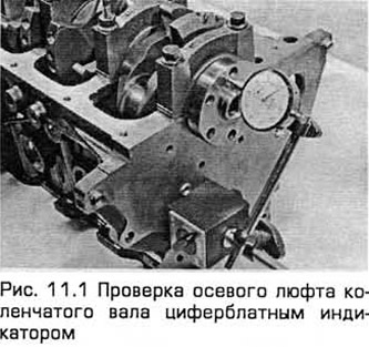
1. Before removing the crankshaft, check its axial play. Install a dial indicator perpendicular to the end of the shaft so that its tip touches the end of the shaft (see Fig. 11.1).
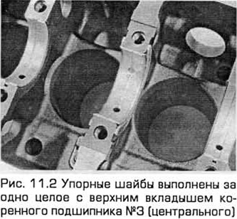
2. Press the shaft completely away from the indicator and reset the indicator. Then press the shaft against the indicator as much as possible and read the readings. This is the axial clearance. If it is greater than the permissible value, check the surfaces of the crankshaft that take up the axial force for wear. If no wear is detected, the axial clearance can be corrected by installing new thrust washers. On models with a 4-cylinder engine manufactured since 05.1998, they are made as a single piece with the upper shell of main bearing No.3 (see Fig. 11.2).
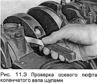
3. If you do not have an indicator, use feeler gauges. Carefully press the crankshaft toward the right end of the engine. Insert the feeler gauge between the shaft and the right end of main bearing No.3 (central) to determine the clearance (see Fig. 11.3).
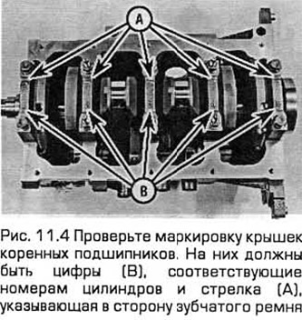
4. On 4-cylinder models, check the main bearing caps to see if they have position markings (see Fig. 11.4). They should have numbers corresponding to the cylinder numbers. If not, use a punch or a special tool to stamp out the numbers. The caps should also have an arrow indicating side 8 of the timing belt. Paying attention to the difference in fastening (for the oil deflector nuts) on caps 2 and 4, loosen the cap bolts a quarter turn at a time, starting with the left and right caps and working towards the middle, until the bolts can be unscrewed by hand.
5. On V6 models, the lower crankcase holds the lower main bearing shells and the crankshaft in the cylinder block. Conventional main bearing caps are not used on these engines. In addition, the inner lower crankcase bolts are disposable and must be replaced with new ones during assembly. Gradually loosen the lower crankcase bolts, then remove them and separate the lower crankcase from the cylinder block. Note the position of the lower main bearing shells.
6. On 4-cylinder models, lightly tap the caps with a soft-faced hammer to loosen them from the cylinder block/crankcase. If necessary, press the caps out with the bolts. Be careful not to let the bearings fall out of the caps if they come off with the caps.
7. Carefully lift the crankshaft. It is better to have an assistant help you, as the shaft is quite heavy. The main bearing shells and caps (4-cylinder engines) or the lower crankcase (V-shaped 6-cylinder engines) should be installed in their places in the cylinder block/crankcase, slightly tightened with bolts. This is necessary in order not to accidentally damage the bearing seats. New shells should be used for installation.
For details, please visit the website [FORDBOOK.RU]