2. Remove the main bearing cap #1. Remove the old bearing shells and clean the connecting rod bearings and caps with a clean, lint-free cloth. They must be perfectly clean!
Checking the working clearance of connecting rod bearings
3. Clean the new upper bearing from the back side and install it into the connecting rod. Then install the other bearing from the kit into the cap. Make sure that the bearing projection fits into the recess in the connecting rod or cap (see Fig. 18.3).
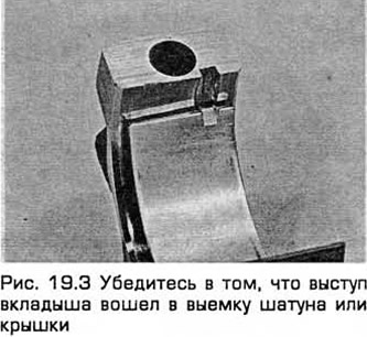
Caution: Do not hammer the bearing shells into place or scratch the bearing surfaces. Do not apply grease at this stage.
4. When installing, the mating surfaces of the bearing components must be perfectly clean and free of grease.
5. Position the piston ring gaps as shown in paragraph 16. Lubricate the piston and rings with clean engine oil and install a piston ring compressor on the piston. Compress the rings until they are flush with the piston.
6. Turn the crankshaft so that the main journal of cylinder No.1 is at bottom dead center and lubricate the cylinder with clean engine oil.
7. Install the connecting rod and piston group of cylinder No.1 so that the arrow on the piston bottom points towards the toothed belt. The numbers corresponding to the cylinder number, etched on the machined surface of the connecting rod and its cover, should be visible from the front (from the engine exhaust side) (see Fig. 9.5,a and 9.5,6). Carefully insert the connecting rod and piston group into cylinder No.1 and rest the lower edge of the piston ring compressor on the cylinder block.
8. Tap the top edge of the ring compressor to ensure it is seated on the block all the way around.
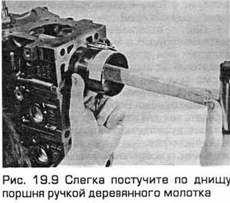
9. Lightly tap the piston crown with the handle of a wooden hammer (see Fig. 19.9), pressing the connecting rod onto the crankpin. Press the compressor with a little force so that the piston rings do not jump out of it before entering the cylinder. Do not rush and if you feel resistance when inserting the piston into the cylinder, stop immediately. Find the cause of the seizure and eliminate it. Do not force the piston into the cylinder under any circumstances, so as not to break the ring and/or piston.
10. To check the working clearance of the connecting rod bearings, cut a piece of plastic thread from the kit of the appropriate size. It should be slightly shorter than the width of the connecting rod bearing. Place the piece of thread on the connecting rod journal of cylinder No.1 parallel to the crankshaft axis (see Fig. 17.6).
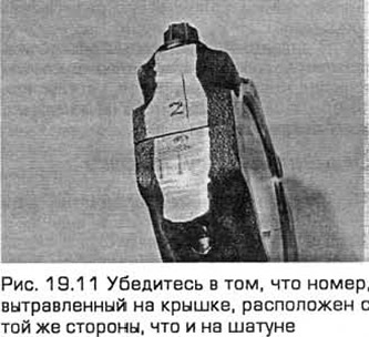
11. Clean the mating surfaces of the connecting rod and cap and install the connecting rod bearing cap. Make sure that the number etched on the cap is on the same side as on the connecting rod (see Fig. 19.11). Tighten the cap bolts evenly - first with a torque wrench to the specified torque, then with a socket and ratchet and a protractor to the specified angle. Use a thin-walled socket so that it does not jam between the cap and nut. If the socket does jam, lift it slightly so that it does not touch the cap. Do not turn the crankshaft while performing this operation!
12. Without moving the thread, unscrew the bolts and remove the cover.
13. Determine the width of the crushed thread using the template to obtain the working clearance. Compare it with the technical requirements.
14. If the clearance does not correspond to the specified, consult with the dealers. If the crankshaft journals are normal, then perhaps to achieve the specified clearance you only need to replace the liners. If this is not possible, then the crankshaft needs to be reground by specialists, who can also sell you liners of the required repair size. Immediately after measuring the working clearance, you need to check that no dirt or oil has gotten between the liners and the connecting rod or cover. You also need to recheck the diameter of the connecting rod journal. If the thread is wider on one side than on the other, then the connecting rod journal may have a taper.
15. Carefully remove any remaining thread from the journal and the working surface of the bearing. Do not scratch the bearing, but use your fingernail or a piece of soft plastic.
Final installation of the connecting rod and piston group
16. Make sure the bearing surfaces are perfectly clean, then lubricate them evenly with clean molybdenum disulphide grease or clean motor oil. Push the piston into the cylinder.
17. Install the connecting rod onto the crankpin, install the connecting rod bearing cap and tighten the bolts in two stages (see above).
18. Repeat the entire procedure for the remaining connecting rod and piston groups.
19. It is important to take into account the following:
- a) The back side of each bearing shell and the connecting rod and cover seat must be perfectly clean when assembled.
- b) Make sure that you insert the connecting rod and piston group into the corresponding cylinder (according to the marking on the front side of the connecting rod and its cap).
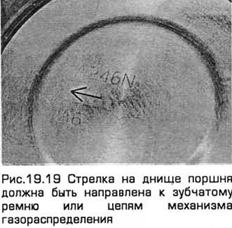
- c) The arrow on the piston bottom must point towards the toothed belt (4-cylinder engines) or timing chains (see Fig. 19.19).
- d) Lubricate the cylinders with clean engine oil.
- d) When installing the connecting rod caps (after completing the operating clearance check), lubricate the working surfaces of the bearings.
20. After installing all connecting rod and piston assemblies, turn the crankshaft by hand a few turns to check for jamming.
21. On 4-cylinder engines produced since 05/1998, apply sealant to the joints between the cylinder block and the oil pump/oil seal housing. Then install a new cylinder block/lower case gasket. Position the lower case on the cylinder block, insert the bolts and tighten them finger tight. Place a straightedge on the transmission mating surfaces of the cylinder block and lower case to check the alignment of the cylinder block and lower case. The lower case should be flush with the cylinder block. If not:
- a) On models with non-automatic transmission, make the adjustment between the position where there is a gap of 0.25 mm between these surfaces and the position where they overlap by 0.1 mm.
- b) On models with automatic transmission, make the adjustment between the position where there is a gap of 0.25 mm between these surfaces and the position where they are flush.
The material was copied from an information website: FordBook.ru