2. Remove the main bearing cap bolts (4-cylinder engines) or lower crankcase (V-6 engines). Remove the caps (and stack them in the proper order for proper installation) or lower crankcase.
3. Remove the old liners from the block and main bearing caps or lower crankcase section. Clean the bearing seats of the block and caps with a clean, lint-free cloth. They must be kept perfectly clean!
Checking the working clearance of main bearings
4. Clean the new main bearing shells from the back side. Install the shells with the oil groove in their places in the cylinder block. Note that on 4-cylinder engines, the thrust washers are made in one piece with the upper shell of main bearing No.3 (central). On V-shaped 6-cylinder engines, the thrust washer in the form of a half ring adjoins the end face of the upper shell of main bearing No.4. Install the other shell from each set in the corresponding main bearing cap (4-cylinder engines) or in the lower crankcase (V-shaped 6-cylinder engines). Make sure that the protrusion of each shell enters the recess in the block or cover. Also note that the oil passages in the block must align with the oil passages of the shells (see Fig. 18.4).
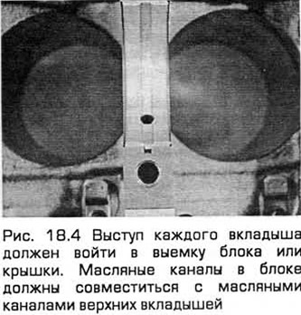
Caution: Do not hammer the bearing shells into place or scratch the bearing surfaces. Do not apply grease at this stage.
5. Clean the working surfaces of the bearings installed in the block, as well as the main journals of the crankshaft with a clean, lint-free cloth. Check or flush the oil passages in the crankshaft, as any dirt will pass through the new bearings.
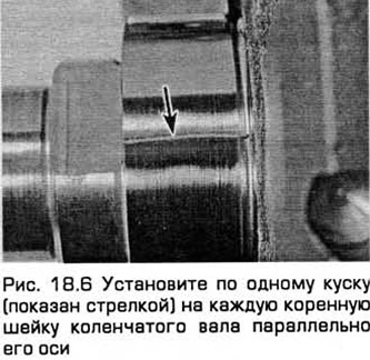
6. The clean crankshaft must be carefully installed in its place in the main bearings. Cut several pieces from the plastic clearance control template of the appropriate size - the cut pieces should be slightly shorter than the width of the main bearings. Install one piece on each main journal of the crankshaft parallel to its axis (see Fig. 18.6).
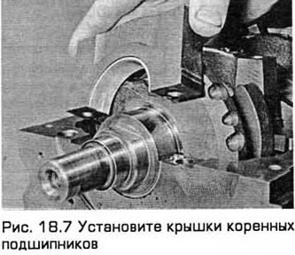
7. Clean the working surfaces of the liners installed in the covers (4-cylinder engines) or the lower crankcase (V-shaped 6-cylinder engines). Install the covers in the appropriate position. (Do not confuse them). The arrows on the covers should point towards the toothed belt. Do not mix up the pieces of the plastic template (see Fig. 18.7).
8. On 4-cylinder engines, tighten the main bearing cap bolts to the specified torque (evenly and without distortion), servicing the caps one by one and starting with the central main bearing and then continuing towards the ends of the crankshaft. Do not turn the crankshaft when performing this operation! On V-6 engines, tighten the lower crankcase bolts (see below).
9. Remove the main bearing cap bolts (lower case) and remove the caps or lower case. Be careful not to damage the measuring thread and do not rotate the crankshaft. If the cap sticks, tap it with a soft-faced hammer.
10. To determine the main bearing operating clearance, compare the width of the flattened thread with the template included in the kit (see Fig. 18.10). Compare the obtained value with Technical requirements.
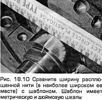
11. If the clearance deviates from the specified value, contact your dealer or engine repair specialist. If the crankshaft journals are normal (see paragraph 13), it is possible that the required clearance can be achieved by replacing the liners. Otherwise, the shaft must be reground and received together with liners of the corresponding repair size. Before deciding to purchase liners of a different size, make sure that there is no dirt or oil between the liners and the bearing bores in the block and in the covers. If the ends of the deformed thread have different widths, then the crankshaft journal is taper.
12. Finally, carefully scrape off any remaining plastic thread from the crankshaft and bearing shells with your fingernail or plastic scraper to avoid scratching the bearing surfaces.
Final installation
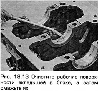
13. Carefully remove the crankshaft. Clean the working surfaces of the bearings in the block, and then lubricate them with a thin, even layer of clean molybdenum disulfide grease or clean motor oil (see Fig. 18.13). Also lubricate the surfaces that absorb axial force.
14. Lubricate the journals under the crankshaft seals with molybdenum disulfide-based grease or clean motor oil.
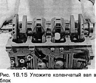
15. Make sure that the crankshaft journals are clean, and then place the shaft in the block (see Fig. 18.15). Clean the working surfaces of the liners located in the covers, and then lubricate them. Install the covers in the appropriate places with the arrows pointing towards the toothed belt.
16. On 4-cylinder engines:
- a) Clean and lubricate the surfaces under the liners in the covers. Install the covers in their original position - with the arrows pointing towards the toothed belt.
- 6) Servicing the covers one by one, starting from the central one and continuing towards the ends of the shaft, tighten their bolts evenly and without distortion to the required torque.
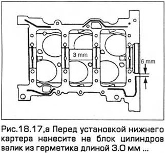
17. On V-shaped 6-cylinder engines:
- a) Apply a 3.0 mm long bead of sealant (see Fig. 18.17,a).
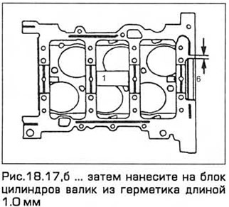
- b) Apply a 1.0 mm long bead of sealant (see Fig. 18.17.6).
- c) Insert the lower crankcase bolts. Tighten the bolts to the specified torque.
18. Turn the crankshaft several revolutions, checking for jamming.
19. Check the shaft axial play (see paragraph 11). It should be normal if the shaft support surfaces are not worn or damaged, and also provided that the bearing shells that absorb the axial force have been replaced.
20. On 4-cylinder engines, install the left crankshaft oil seal housing, and then insert the new oil seal (chapter 2A paragraph 20).
21. On V-shaped 6-cylinder engines, install a new cuff (chapter 2B).