Contents: Cleaning ↳ Control ↳
Cleaning
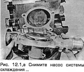
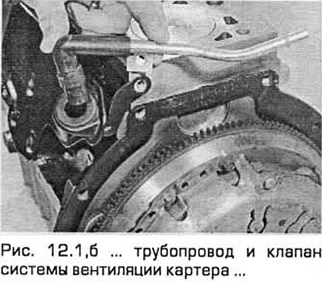
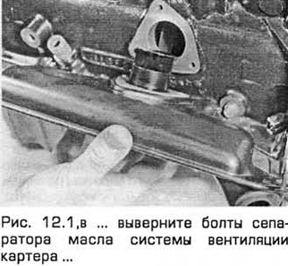
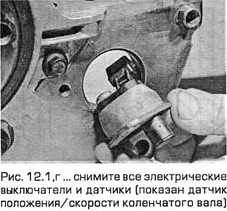
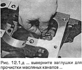
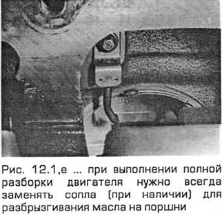
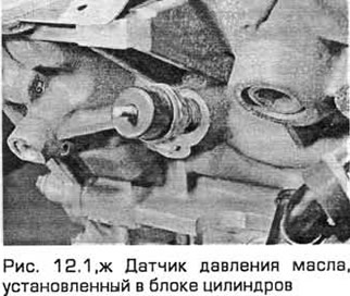
1. To perform a complete cleaning, remove the coolant pump, all external components, and all electrical switches and sensors. Unscrew the piston oil spray nozzles or the plugs installed in their place. Note that when performing a complete disassembly of the engine, it is always necessary to replace the piston oil spray nozzles (if any) (see Fig. 12.1, a-g).
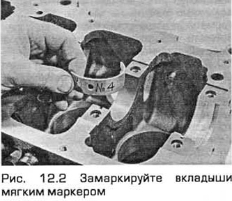
2. Remove the main bearing caps and separate the bearing shells from the caps and from the cylinder block/crankcase. Mark the bearing shells to indicate which cap or location in the cylinder block they came from, then stack them (see Fig. 12.2). Wipe the bearing shell areas in the block and caps and inspect them for scratches and nicks.
3. Scrape off the remains of the old gasket from the cylinder block/crankcase, but without damaging the sealing surfaces.
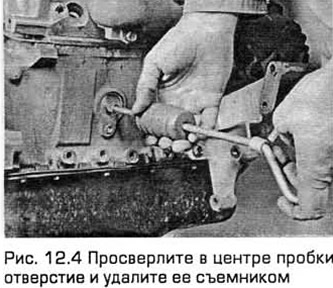
4. Remove all oil channel plugs (if any). They are usually tightly tightened. Therefore, they can be drilled out and new threads cut in the holes. When assembling the engine, use new plugs. Also remove the technological plugs from the cylinder block walls. Try to knock them out with a hammer, striking through the punch on the side of the plug, trying to turn it in the hole. If you succeed, grab the plug by the edge with large pliers and pull it out of the hole. Alternatively, drill a hole in the center of the plug and remove it with a puller (for bodywork), (see Fig. 12.4).
Please note: If you drive a technological plug into a hole, it will be very difficult, and often impossible, to pull it out.
5. If cast surfaces are significantly contaminated, they must be cleaned with steam.
6. After steaming, clean all oil passages and holes again. Rinse all internal passages with hot water until the water runs clear. Dry thoroughly and apply a thin layer of grease to all mating surfaces to prevent corrosion. Lubricate the cylinder bores. If compressed air is available, use it to speed up drying and blow out oil passages and holes.
Warning: Protect your eyes when using compressed air!
7. If the castings are slightly dirty, they can be cleaned with a solution of soap and hot water and a stiff brush. The water should be as hot as possible. Take the time to do this job thoroughly. Regardless of the cleaning method used, carefully check the cleanliness of all oil passages and holes and thoroughly dry all parts and assemblies. Protect the cylinder bores from corrosion as described above.
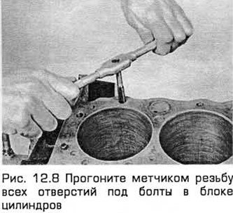
8. All threaded holes must be cleaned to ensure the specified tightening forces during assembly. To do this, run a tap through the threads to remove rust, grease residue or dirt, and to restore damaged threads (see Fig. 12.8). If possible, blow out the holes with compressed air.
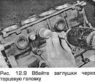
9. Apply sealant to the seating surfaces of the cooling jacket plugs and install them in the cylinder block. Ensure that they are installed correctly without any distortions, otherwise leaks may occur. Apply sealant to the new oil channel plugs and insert them into the cylinder block holes. Tighten the plugs securely (see Fig. 12.9).
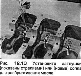
10. Install the plugs or (new) oil spray nozzles on the piston crowns. Tighten them to the specified torque (see Fig. 12.10). Also install any other external components that were removed. Install the main bearing caps (4-cylinder engines) or lower crankcase (V-6 engines) and tighten them finger tight.
11. If you are not going to assemble it right away, cover the engine with a large plastic bag to protect the engine from dirt. Protect the mating surfaces from corrosion by lubricating them with engine oil.
Control
12. Check the cast surfaces for corrosion and cracks. Inspect the threaded holes for damaged threads. If water leaks are detected inside the engine, have the cylinder block/crankcase checked by specialists using special equipment. If defects are detected, the cylinder block/crankcase must be repaired or replaced (see Fig. 12.12).
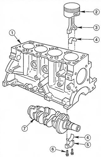 Fig. 12.12 Cylinder block, connecting rod with piston and crankshaft parts (4-cylinder engines)
1. Cylinder block/crankcase
2. Piston
3. Connecting rod
4. Connecting rod bearing shell
5. Connecting rod bearing cap
6. Connecting rod bearing cap bolts
7. Crankshaft
13. Inspect the surfaces of all cylinders for scratches and burrs.
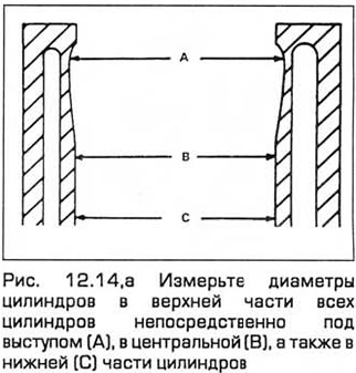
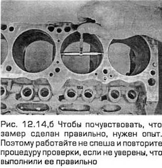
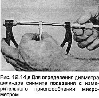
14. All main bearing cap bolts (4-cylinder engines) or lower crankcase bolts (V-6 engines) must be tightened to the specified torque, provided that the crankshaft and liners are absent. Measure the diameters of all cylinders in a direction parallel to the crankshaft axis: at the top of the cylinder (directly under the projection), in the center, and at the bottom of the cylinder. Then measure the diameters of the cylinders in a direction perpendicular to the crankshaft axis in the same sections (see Fig. 12.14, a-c). Record the measurement results.
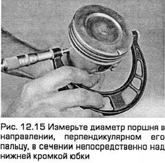
15. Measure the piston diameter in the direction perpendicular to its pin, in the section directly above the lower edge of the skirt. Record the measurement results (see Fig. 12.15).
16. If you want to determine the clearance between the piston and the cylinder, measure the diameters of the cylinder and the piston skirt as described above and subtract the skirt diameter from the cylinder diameter. If you do not have precise measuring instruments, the condition of the pistons and cylinders can be checked, but with less accuracy, using feeler gauges as follows. Select a feeler gauge of a thickness equal to the specified clearance between the piston and the cylinder and insert it into the cylinder together with the corresponding piston. The piston must be installed in its working position. And the feeler gauge must be inserted from one of the sides of the cylinder experiencing axial force (at a right angle to the piston pin). The piston should slide along the cylinder (relative to the fixed feeler gauge) with little force. If it slides without any resistance at all, then the clearance is too large and therefore a new piston must be installed. If the piston sticks at the bottom edge of the cylinder, but moves freely at the top, then the cylinder is conical. If, when turning the piston inside the cylinder together with the feeler gauge, you feel areas of sticking, then the cylinder is out of round (oval).
17. Repeat these procedures for the remaining pistons and cylinders.
18. Compare the results with the Specifications. If any of the measurements deviate from the permissible limits (for the given class - see the marking on the piston crown), or if the cylinder diameters differ significantly from each other (indicating taper or ovality), then the piston or cylinder is excessively worn.
19. Worn pistons should be replaced. At the time of writing, pistons were not supplied separately, but only as part of a connecting rod and piston group. Consult your dealer for the latest information.
20. If one of the cylinders has deep nicks or scratches or is excessively worn or has a large ovality or taper, then proceed in the usual way. That is, regrind the cylinder block/crankcase and install new pistons of the repair size.
21. If the cylinders are in good condition and not worn, then only the piston rings can be replaced.
22. In this case, and if new piston rings are available, the cylinders must be honed so that the new piston rings are properly seated and provide a reliable seal. Before honing the cylinders, install the main bearing caps (without inserting the liners) and tighten the bolts to the specified torque.
Note: If you do not have the special equipment or do not want to do honing, then this operation can be performed by engine repair specialists for a small fee.
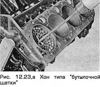
23. There are two types of hones for honing cylinders - a flexible or "bottle brush" hone and the more familiar spring-loaded stone hone. Both types of hones are suitable for this job and are usually mounted on an electric drill. For the less experienced car owner, a "bottle brush" is more convenient. You will also need some kerosene or honing oil and a rag. Follow these instructions:
- a) Insert the techon into the hole, squeeze the stones and pull it in (see Fig. 18.S3,a). Put on protective glasses or a shield!
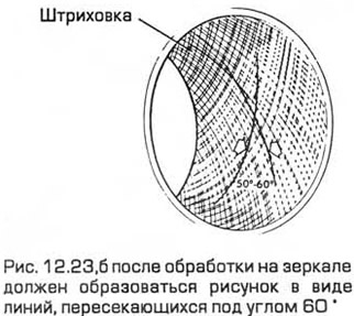
- b) Lubricate the bore with honing oil. Turn on the electric drill and move the hone up and down the bore to create a grid pattern on the cylinder walls. Ideally, the grid lines should intersect at an angle of 80° (see Fig. 13.23.6). Do not use too much lubricant.
Note: Piston ring manufacturers may specify the angle at which the lines intersect when honing. Read the ring instructions carefully.
- c) Do not pull the hone out of the hole while it is rotating, but instead turn off the drill and continue to move the hone up and down the hole until it stops completely. Then squeeze the stones and pull the hone out. If you are using a bottle brush, turn off the drill, then rotate the drill chuck in the direction of its working rotation to pull the hone out of the hole.
- d) Wipe the cylinder to remove oil and repeat the procedure for the remaining cylinders.
- d) After honing all cylinders, chamfer the edges of the bores with a fine-cut file so that the rings do not bind when installing the pistons. Be careful not to nick the cylinder walls.
- e) The entire cylinder block/crankcase should be washed with warm soapy water to remove any dirt from honing.
Note: The cylinders are clean when you press a white, lint-free cloth soaked in clean engine oil against the cylinder walls and rub them, and after doing so, you do not find any particles left over from honing, which appear on the cloth as gray spots. Clean all oil passages with a brush and flush them with a stream of water.
- g) After cleaning the cylinder block/crankcase, dry it and then lightly lubricate all machined surfaces to prevent rust.
24. The engine block/crankcase is now completely clean and dry, and all components are checked for wear or damage and repaired if necessary. Install as many accessories as possible. If you are not reassembling the engine immediately, cover the block with a large plastic bag to keep it clean and prevent the machined surfaces from rusting.
If you do not have a device for extracting piston rings, you can remove them by hand. Carefully spread the ends of the rings over the surface of the piston head. To prevent the rings from sinking into empty grooves, use 2-3 used feeler gauges.