See Warnings and Notes paragraph 4.
Duratec engines
Removal
Note: Ford service centers use a special device to align the power unit with the subframe. Before removing the power unit, mark the position of the engine mounts.
1. Place the vehicle on a level, horizontal surface and apply the parking brake.
2. Disconnect and remove the battery (Chapter 5A).
3. Insert pieces of wire into the upper radiator support to secure it in place after it is disconnected from the lower supports.
4. Unscrew the bolts and remove the top engine cover. Also release the coolant hose from the clamp.
5. Raise the front end (enough to allow the power unit to be removed from underneath the vehicle) and place it on supports. Remove both front wheels.
6. From under the car, unscrew the screws and remove the lower radiator cover.
7. Drain the cooling system (Chapter 10).
8. Place a container under the transmission. Then remove the drain plug to drain the oil. Clean the plug and tighten it securely.
Warning: Drain the oil only when the engine is cool!
9. Disconnect the accelerator cable from the throttle body (Chapter A). Move the cable to the side.
10. Disconnect the cruise control cable from the throttle body (Chapter 12). Move the cable to the side.
11. Loosen the clamps and disconnect the positive crankcase ventilation hoses on both sides of the air duct connecting the air cleaner to the throttle body.
12. Loosen the clamps and disconnect the air duct connecting the air cleaner and the throttle body.
13. Loosen the clamps and disconnect the vacuum hose from the EGR valve on the left side of the rear cylinder head.
14. Disconnect the wiring from the sensor located on top of the air flow meter. Disconnect the wiring from the intake air temperature sensor located on the rear of the air cleaner cover.
15. Remove the air cleaner (Chapter 4A).
16. Loosen the clamps and disconnect the brake booster vacuum hose from the upper section of the intake manifold.
17. Wrap a rag around the fuel pressure relief valve. Then remove the cover screws and use a screwdriver to press the center pin to release any residual pressure in the fuel system. Then install the cover.
18. Disconnect the fuel supply and return lines from the left side of the engine and move them to the side. Their quick-release connections must be disassembled using a special tool (Chapter 4A).
19. Loosen the clamps and disconnect the hoses from the coolant distribution pipe located on the left edge of the cylinder heads. Disconnect the upper hose from the radiator and thermostat housing.
20. Remove the ground wire bolts from the transmission. Remove the bolt and disconnect the main wiring harness connector in the left engine compartment and release the wires from the battery support bracket.
21. On models with a non-automatic transmission, disconnect the selector linkage or cables (Chapter 7A). Disconnect the clutch hydraulic line on top of the transmission (Chapter 6). To prevent leaks, pinch the hose directly below the brake fluid reservoir.
22. On models with automatic transmission, remove the selector cable bracket bolts on the side of the transmission and disconnect the end of the cable from the lever (Chapter 7B).
23. Disconnect the wiring from the starter (Chapter 5A). Where necessary, remove the plastic cover to access the terminals.
24. Disconnect the two fan electrical connectors located on the left side of the radiator and release the wiring harness.
25. In the right rear corner of the engine compartment, remove the power steering reserve tank from its supports, move it to the side and place it without tilting it.
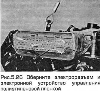
26. Remove the engine wiring ground bolt located on the left inner fender panel, behind the headlight. Disconnect the engine wiring harness from the traction control module. On late-model models, rivets must be drilled out to remove the cover. Remove the bolt and disconnect the electrical connector. To prevent dust or dirt from getting into the connector, wrap the electrical connector and the electronic control unit in plastic film (see Fig. 5.26). Pull the wiring harness out on top of the engine.
27. Label the hoses. Then release the clamps and disconnect the three hoses from the coolant reserve tank in the right front corner of the engine compartment. Remove the screws and lift the tank out of the inner fender panel.
28. Disconnect the heater vacuum hoses at the rear of the engine.
29. At the rear left side of the cylinder head, disconnect the evaporative emission control system hose from the throttle body.
30. At the rear of the engine, release the wiring from the fasteners and disconnect it from the oxygen sensor.
31. Remove the bolts and fork section of the exhaust system and the rear catalytic converter from both exhaust manifolds and the intermediate section (Chapter 4A). Remove the gaskets.
32. Remove the mudguards from under the wheel arches, having first unscrewed their screws.
33. Remove both drive shafts (Chapter 8). To do this, remove the clamp bolts and disconnect the lower arm ball joints from the steering knuckles. Tie the suspension struts to prevent damage to the rubber boots of the ball joints.
34. Unscrew the bolts and remove the heat-insulating casing covering the steering gear.
35. Remove the steering gear bolts and tie it to the engine compartment bulkhead. Use the special key (Chapter 10). If you do not have one, the bolts can be removed after lowering the subframe (see below). Note that the steering gear pinion remains connected to the bottom of the steering column.
36. Remove the nuts/bolts and center bolt from the rear engine mount and remove it along with the bracket. Use a jack or lift if necessary. Also remove the mount bolts from the transmission.
37. Unscrew the bolts securing the front support to the subframe, and also unscrew the central bolt. Remove the support.
38. On models with air conditioning, remove the moisture separator bolts from the subframe on the left side. Move the moisture separator to the side and tie it down without disconnecting the lines.
39. On late model models, loosen the short pillar threads on both sides of the subframe.
40. On models with automatic transmission, remove the transmission line bracket bolts from the front of the subframe.
41. Remove the bolts of the hydraulic steering system pipe bracket from the subframe on its right side.
42. Before removing the subframe, mark its position. Please note that Ford service centers use a special device to align the subframe during installation.
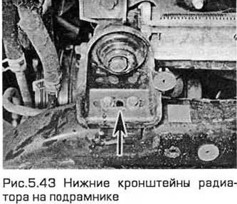
43. Support the subframe with a jack using a wooden block. Remove the bolts, then carefully lower the subframe. If necessary, remove the steering gear bolts while lowering the subframe. When the subframe is lowered, make sure that the radiator is out of its lower rubber bushings and that the bracket bolts can be removed from the subframe (see Fig. 5.43).
44. Disconnect the wiring from the vehicle speed sensor on the rear of the transmission.
45. On models with air conditioning, disconnect the wiring from the compressor and water separator and lay it on top of the engine.
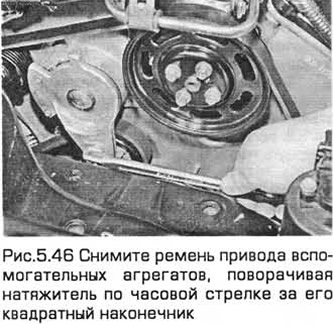
46. Remove the accessory drive belt by turning the tensioner clockwise by its square end (3/8'), (see Fig. 5.46). Before removing, check the position of the protrusion in relation to the bracket stops. If the protrusion touches the right stop, the belt has stretched to the limit and must be replaced.
47. On models with air conditioning, remove the insulation housing bolts from the compressor.
48. Loosen the clamp and remove the lower radiator hose.
49. Unscrew the union nut and disconnect the oil cooler pipe from the radiator. Prepare to eliminate leaks.
50. On models with automatic transmission, unscrew the union nuts and disconnect the transmission cooler fluid pressure and drain lines from the transmission. Plug the resulting holes. Then unscrew the transmission drain line bolts.
51. On models with air conditioning, remove the condenser-to-radiator bolts and tie the condenser to the engine compartment crossmember. Remove the compressor bolts from the engine block and place it on the engine compartment crossmember, then tie it to it. Remove the bolts and refrigerant line bracket from the coolant line. Do not disconnect the refrigerant lines.
52. Remove the pieces of wire inserted earlier to secure the radiator, then lower the radiator into the engine compartment, and then remove it from the car. If necessary, remove the upper rubber radiator mounts from the crossmember. The radiator is installed tightly in the mounts and must be removed carefully.
53. To improve access, remove the electric fan impellers and casing before removing the radiator (Chapter 3).
54. Using a lift, lift the power unit by the lifting eyes located at the front left and rear right.
55. Remove the right engine mount bolts and the upper mount bracket. Remove the bolts and the lower mount bracket from the right wing inner panel.
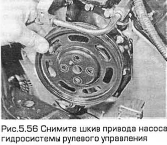
56. Remove the power steering pump drive pulley bolt (see Fig. 5.56). Hold the pulley with a belt wrench designed for the oil filter. Remove the bolts/nuts and remove the power steering pump from the right engine mount bracket. Lean the pump with its pipes against the engine compartment bulkhead and tie it to the windshield wiper shaft.
57. Remove the nuts securing the left engine mount bracket to the transmission. If necessary, remove the bolts of this bracket from the inner wing panel.
58. Carefully lower the power unit to the floor. Try not to touch the body and steering components. If possible, lower the power unit onto a low dolly, which will make it easier to remove the unit from under the car.
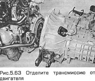
Separation
59. Remove the starter bracket bolts and remove it. Then remove the starter bolts from the transmission housing.
60. Disconnect and unfasten the wiring of the following components:
- a) Speed sensor
- b) Electrical control connector (automatic transmissions)
- c) Engine coolant temperature sensor
- d) Transmission operating mode sensor (automatic transmissions)
61. On models with automatic transmission, remove the plastic cover and unscrew the nuts securing the torque converter to the faceplate. This will require turning the engine to access the nuts.
62. Remove the transmission-to-engine mounting bolts. Some of these are located on the right side of the transmission.
63. With the help of an assistant, carefully separate the transmission from the engine (see Fig. 5.63). On models with a non-automatic transmission, make sure that the weight of the transmission does not load the clutch disc. On models with an automatic transmission, make sure that the torque converter is connected to the pump on the transmission output shaft.
Installation
64. Make sure the adapter plate is installed on the dowel pins.
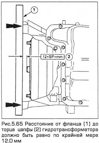
65. On models with automatic transmission, make sure that the torque converter is fully connected to the pump on the transmission output shaft. To check this, measure the distance from the flange to the end of the torque converter journal with a ruler. It should be at least 12.0 mm (see Fig. 5.65), set the transmission selector to the "D" position. Lubricate the journal with high-melting grease.
66. With the help of an assistant, carefully connect the transmission to the engine. On models with automatic transmission, the mounting studs should fit into the holes in the faceplate.
67. Insert the bolts into the transmission flange and tighten them to the specified torque.
68. On models with automatic transmission, turn the engine and tighten the torque converter nuts to the specified torque.
69. Perform the remaining installation procedures in the reverse order of removal, taking into account the following:
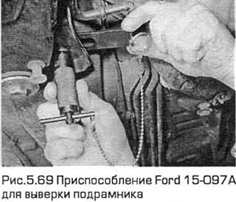
- a) When installing the subframe, you will need the Ford 15-097A device (see Fig. 5.69) to check its position before tightening the bolts. If you do not have such a device, align the subframe using the marks.
- b) Install the engine mounts using the marks made before removal. The front engine mount tool is used to align the engine with the subframe when installing the rest of its mounts. This tool should be installed on the subframe instead of the front engine mount so that the arrow on it points forward. If you do not have such a tool, install the mounts using the marks.
- c) Tighten all bolts and nuts to the specified torque
- d) Remove air from the clutch hydraulic system (Chapter 6)
- d) Adjust the accelerator cable (Chapter 4A) and the cruise control cable (Chapter 12)
- e) Top up the cooling system and remove air from it (chapter 1)
(The original version can be found on the website: FORDBOOK.RU)