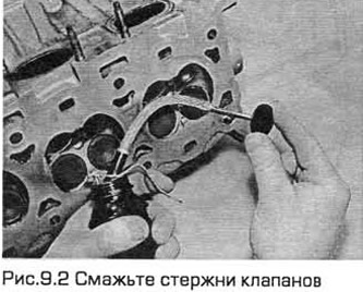
2. Lubricate and install the valves one at a time, starting from the edge of the head. Lubricate the valve stems with molybdenum-based grease or clean motor oil (see Fig. 9.2). If you are installing valves that have already worked, insert them into their places. If you are installing new valves, insert each valve in the position in which it was ground in.
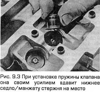
3. Install the plastic protectors supplied with the lower spring seat/stem sleeve onto the end of the valve stem. Then push the new sleeve straight onto the top of the guide and leave it in this position. When the valve spring is installed, it will press the lower spring seat/stem sleeve into place (see Fig. 9.3).
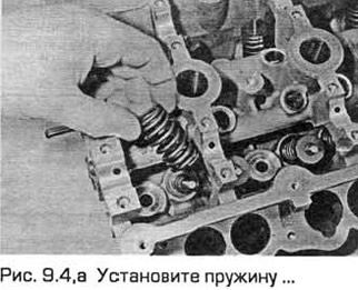
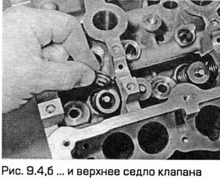
4. Install the spring and the upper valve seat (see Fig. 9.4,a,b).
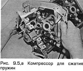
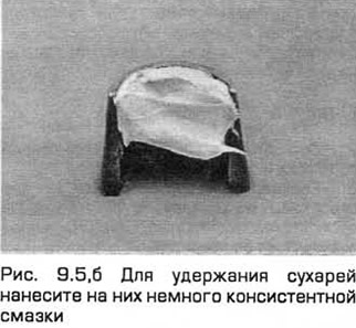
5. Compress the spring with a valve spring compressor and carefully insert the crackers into the groove of the rod. If necessary, apply a small amount of grease to the crackers to hold them in place (see Fig. 9.5,a,b). Slowly release the compressor and make sure that the crackers are seated in place.
6. After installing the valve, place the cylinder head on the workbench and tap the end of the stem through a wooden block with a hammer to install the valve components.
7. Repeat the procedure for the remaining valves, installing the components in their places.
8. Install the hydraulic valve clearance compensators (chapter 2A or 2B).