Special tool
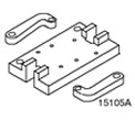 | Engine/Differential Support Bracket 205-329 (15-105A) |
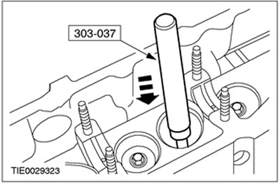
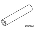 | Valve stem seal installer 303-037 (21-007A) |
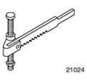 | Valve Spring Compressor 303-060 (21-024) |
 | Adapter for 303-060 (21-024) 303-060-05 (21-024-05) |
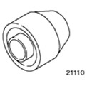 | Camshaft seal installer 303-199A (21-110A) |
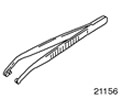 | Valve stem cotter installer 303-362 (21-156) |
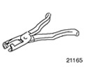 | Pliers for valve stem seals 303-390 (21-165) |
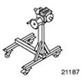 | Support stand 303-435 (21-187) |
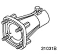 | Support bracket for 303-435 303-435-06 (21-031V) |
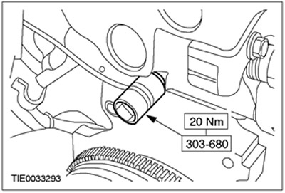
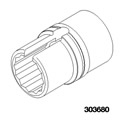 | Socket wrench for cylinder head temperature sensor 303-680 (21-239) |
| Name | Specification |
| sealant | WSK-M2G348-A5 |
| hypoid oil | SQM-2C-9002-AA |
| Engine oil | WSS-M2C912-A1 |
Disassembly
All cars
WARNING: Do not smoke or walk with a lit cigarette or any type of open flame while working on or near fuel related items. In such situations, there are always highly flammable mixtures that can ignite. Failure to follow these instructions. Failure to follow these instructions may result in injury.
WARNING: This procedure is related to fuel handling. Always be aware of the possibility of fuel splashing and observe fuel handling precautions. Failure to follow these instructions may result in injury.
CAUTION: Diesel fuel injection equipment is manufactured to very precise tolerances and very close clearances. Therefore, it is especially important to observe absolute cleanliness when working with these elements. Always insert plugs into any open holes or lines.
CAUTION: Do not disassemble fuel injectors or clean their nozzles, even with ultrasonication.
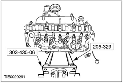
1. Using special tools, secure the cylinder head to the support stand.
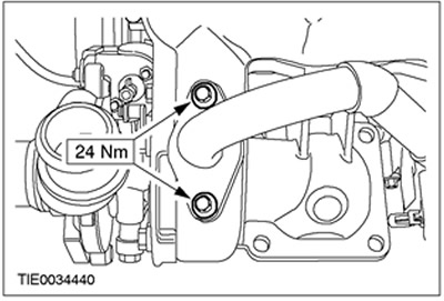
Vehicles with an EGR cooler (EGR)
2. Turn out bolts of a flange of the final pipeline of a cooler EGR.
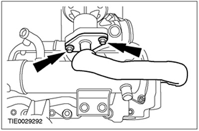
3. Remove the EGR cooler flange bolts. Discard the gasket as it is no longer needed.
4. Remove the EGR cooler.
Vehicles without EGR cooler
5. Disconnect the EGR pipeline from the EGR valve.
6. Remove the EGR pipeline.
All cars
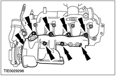
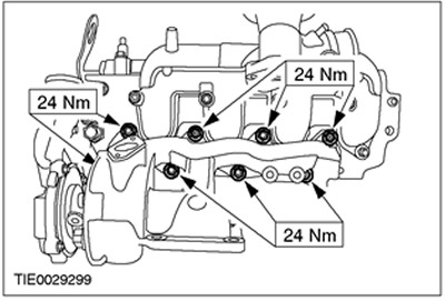
7. Remove the exhaust manifold (six bolts and two self-locking nuts). Discard the gasket, bolts and nuts as they are no longer needed.
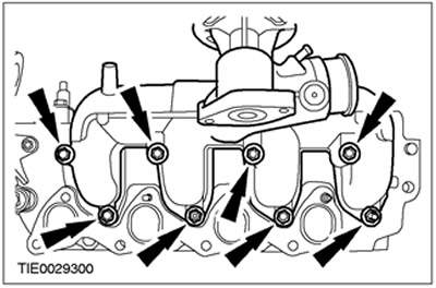
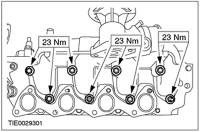
8. Remove intake manifold (six bolts and two self-locking nuts). Discard the gasket, bolts and nuts as they are no longer needed.
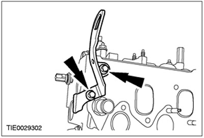
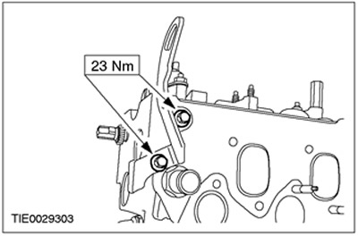
9. Remove the rear engine lifting eye.
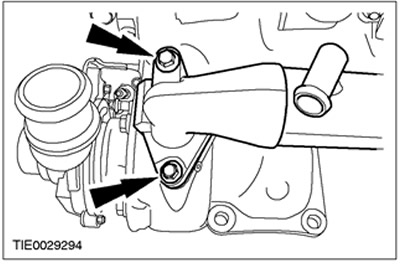
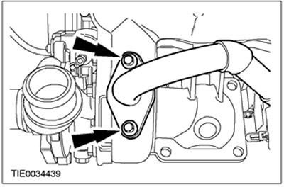
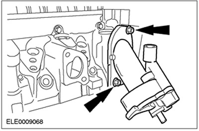
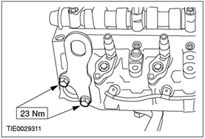
10. Remove the coolant outlet pipe. Discard the pipe as it is no longer needed.
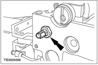
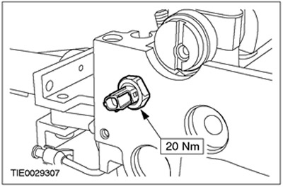
11. Remove the oil pressure switch.
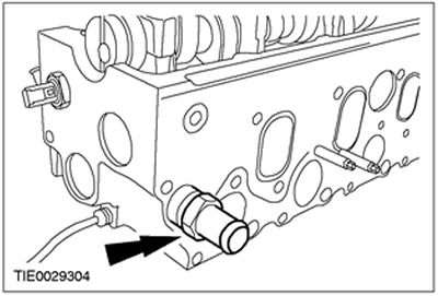
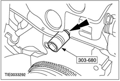
12. Using the special tool, remove the cylinder head temperature sensor (CHT). Discard the sensor as it is no longer needed.
13. Remove the front engine lifting eye.
14. Remove the glow plug wiring harness.
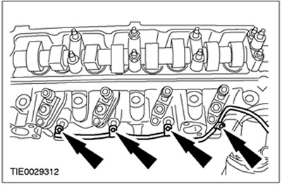
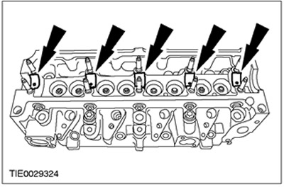
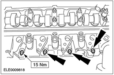
15. Turn out bolts of fastening of clips of fuel atomizers. Discard the bolts as they are no longer needed.
16.
NOTE: Mark the position of the fuel injectors to ensure they are installed in their original position.
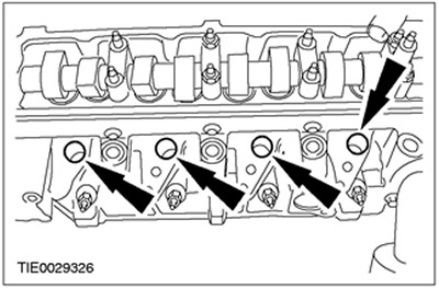
Remove the fuel injectors and retaining clips. Discard the fuel injector sealing washers as they are no longer needed.
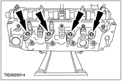
17. Remove glow plugs.
18.
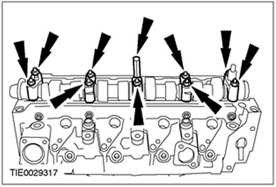
CAUTION: Loosen all nuts and bolts of the camshaft bearing caps one turn just enough to loosen the camshaft.
NOTE: Mark the positions of the camshaft bolts and bearing caps to ensure they are in their original position.
Remove the camshaft. Discard the camshaft oil seal as it is no longer needed.

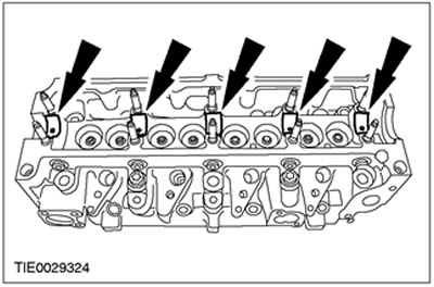
19.
NOTE: Mark the positions of the valve lifters and shims to ensure they are in their original position.
Remove the valve lifters and valve shims.
20.
NOTE: Mark the position of the lower camshaft bearing shells to ensure they are installed in their original position.
Remove the lower camshaft bearing shells.
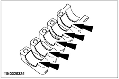
21.
NOTE: Mark the position of the camshaft bearing cap shells to ensure they are in their original position.
Remove the camshaft bearing caps.

22. Remove the vacuum pump of the vacuum amplifier of brakes. Discard the O-ring as it is no longer needed.
23. Remove a pusher of a drive of the vacuum pump of the vacuum amplifier of brakes.

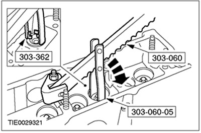
24. Using the special tools, remove the valve stem cotters.
25.
NOTE: Mark the position of the valve springs and valve discs to ensure they are in their original position.
Remove valve springs with valve plates.
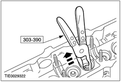
26. Using the special tool, remove the valve stem seals. Discard the oil seals as they are no longer needed.
27.
NOTE: Mark the position of the valves to ensure they are in their original position.
Remove valves.
Assembly
All cars
1. Apply clean hypoid oil to the valves.
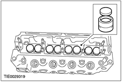
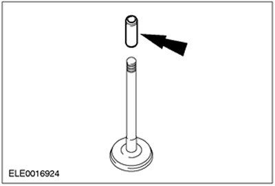
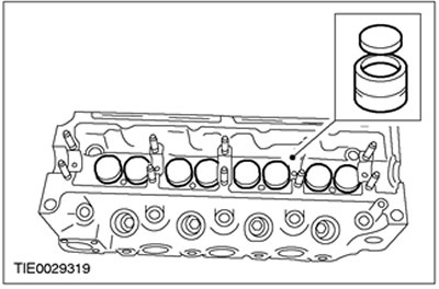
2. Install the process sleeves on the valve stems, covering the valve cotter grooves (for clarity, the valve is shown removed).
3.
NOTE: Install new valve stem seals.
Using the special tool, install the valve stem seals.
4. Remove process bushings from valve stems.
5. Install valve springs and valve plates.
6. Using the special tools, install the valve stem cotters.

7. Remove special tools.
8. Apply clean engine oil to the brake booster vacuum pump drive tappet.
9. Establish a pusher of a drive of the vacuum pump of the vacuum amplifier of brakes.
10.
NOTE: Install a new brake booster vacuum pump O-ring.
Install the brake booster vacuum pump.
11. Establish loose leaves of covers of bearings of a camshaft.
12. Apply clean engine oil to the camshaft bearing caps.
13. Establish the bottom loose leaves of bearings of a camshaft.
14. Apply clean engine oil to the lower camshaft bearing shells.
15. Apply clean engine oil to the valve lifters and shims.
16.
NOTE: Lettering on valve shims faces down.
Install the valve lifters and valve shims.
17.
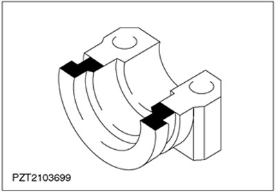
NOTE: The larger semicircle should face up.
Install the camshaft to the cylinder head.
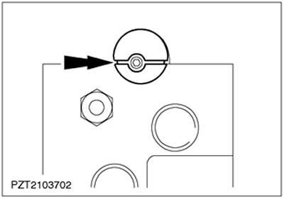
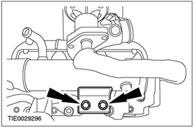
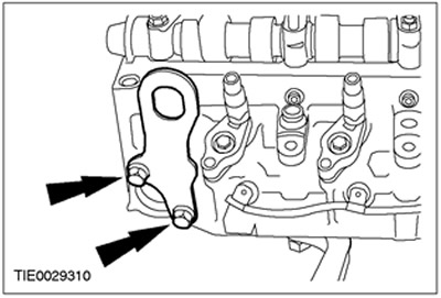
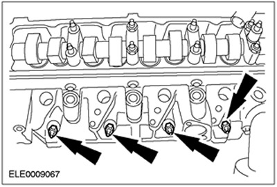
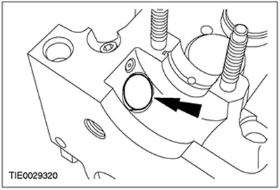
18. Apply sealant to #1 bearing cap at the locations shown.
19.
NOTE: The arrows on the camshaft bearing caps must point towards the front of the engine.
NOTE: Do not tighten the camshaft bearing caps at this stage.
Install the camshaft bearing caps.
20.
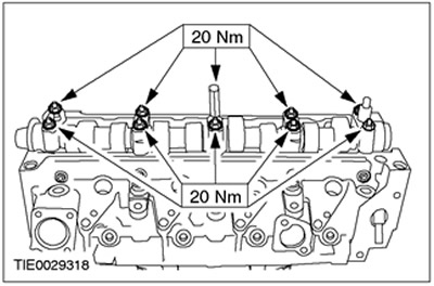
NOTE: Tighten the camshaft bearing cap nuts and bolts, working evenly, one turn at a time.
Tighten the nuts and bolts of the camshaft bearing caps.
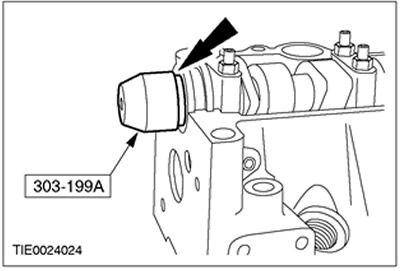
21.
NOTE: Install a new camshaft oil seal.
Using the special tool, install the camshaft oil seal.
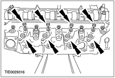
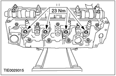
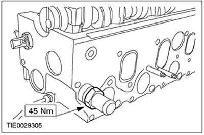
22. Install glow plugs.
23.
NOTE: Install new fuel injector seal washers.
Install the fuel injector seals.
24. Install fuel injectors and retaining clips.

25.
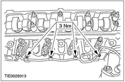
NOTE: Install new fuel injector clamp bolts.
Install the fuel injector clamp bolts.
26. Install the glow plug harness.
27. Install the front engine lift eye.
28.
NOTE: Install a new cylinder head temperature sensor (CHT).
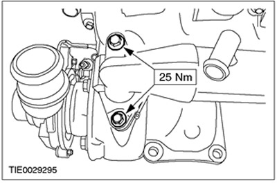
Using the special tool, install the CHT sensor.
29. Install an oil pressure switch.
30.
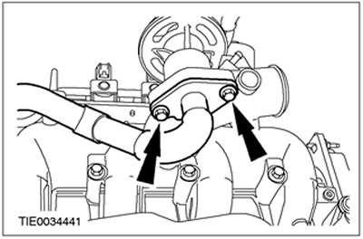
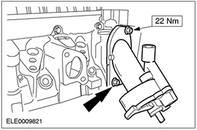
NOTE: Install a new coolant outlet pipe.
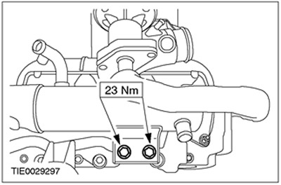
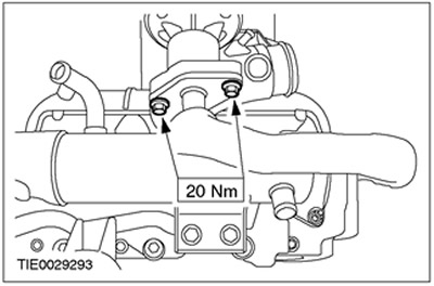
Install the coolant outlet pipe.
31. Install the rear engine lifting eye.
32.
NOTE: Install a new intake manifold gasket and new self-locking nuts and bolts.
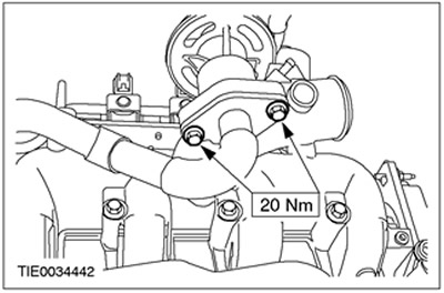
Install the intake manifold.
33.
NOTE: Install a new exhaust manifold gasket and new self-locking nuts and bolts.
Install the exhaust manifold.
Vehicles without EGR cooler
34.
NOTE: Do not tighten the upper EGR pipe bolts at this stage.
Install the EGR pipe top bolts.

35. Install the EGR pipeline.
36. Tighten the EGR pipe top bolts.
Vehicles with EGR cooler
37. Install the EGR cooler.
38.
NOTE: Install a new EGR cooler flange gasket.
Install the EGR cooler flange bolts.
39. Install the EGR cooler exhaust pipe flange bolts.
All cars
40. Disconnect the cylinder head from the support stand. Remove special tools.

Visitor comments