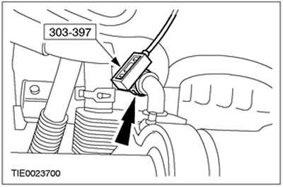
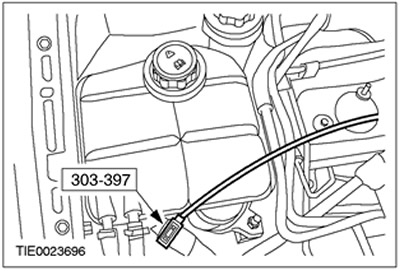
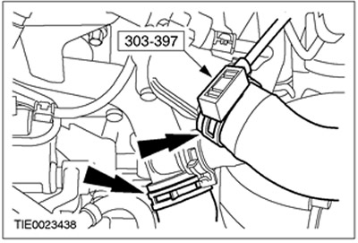
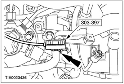
Special tool
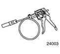 | Clamp removal/installation tool 303-397 (24-003) |
General equipment:
- Workbench
- Fixing clamp
| Name | Specification |
| Anti-seize lubricant | SAM-1C9107-A |
All cars
1.
WARNING: Do not smoke or carry a lighted cigarette or open flame of any type when working on or near fuel-related components. Highly flammable mixtures are always present in such situations and may ignite. Failure to follow these instructions may result in injury.
Install the gearbox in block with the drive axle on the engine.
2. Raise and support the vehicle. Refer to Section 100-02 for additional information.
3.
WARNING: Support the engine and transaxle assembly on wooden blocks. Failure to follow this instruction may result in personal injury.
CAUTION: Support the engine under the oil pan flange.
Using suitable clamps, secure the engine/transmission assembly to the work bench and position the unit under the vehicle.
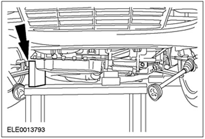
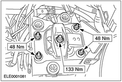
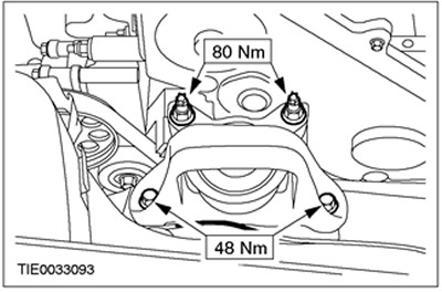
4. Install the rear engine mount.
Cars manufactured up to 04.2001.
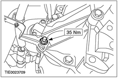
5. Install the front engine mount.
Cars manufactured since 04.2001.
6. Install the front engine mount.
All cars
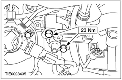
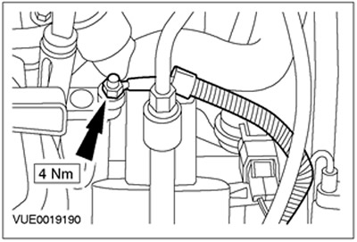
7. Connect the starter wiring harness bracket and engine ground cable to the transaxle housing.
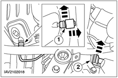
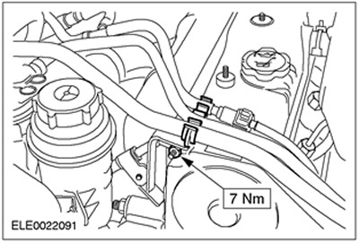
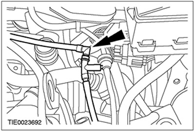
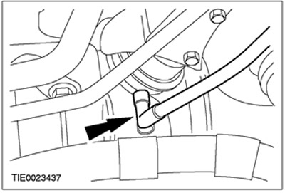
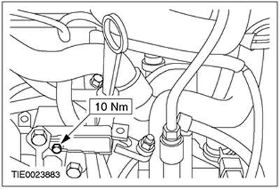
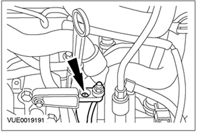
8. Connect the high pressure line to the clutch slave cylinder.
- 1.Install the clamp.
- 2. Attach the bracket with rubber sealing rings.
9.
CAUTION: Secure the axle shaft to prevent damage to the constant velocity joints. The inner constant velocity joint should not be deflected more than 18 degrees. The outer constant velocity joint should not be deflected more than 45 degrees.
CAUTION: Make sure the axle shaft seal is not damaged.
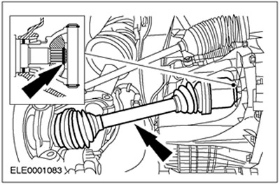
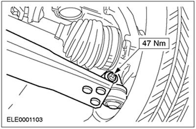
Connect the left axle shaft to the transaxle.
10.
CAUTION: Secure the axle shaft to prevent damage to the constant velocity joints. The inner constant velocity joint should not be deflected more than 18 degrees. The outer constant velocity joint should not be deflected more than 45 degrees.
CAUTION: Make sure the axle shaft seal is not damaged.
NOTE: Install a new center support bearing cap and locknuts.
Connect the right axle shaft to the transaxle block and install the bearing cap.
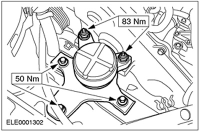
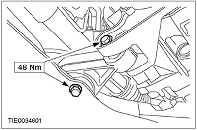
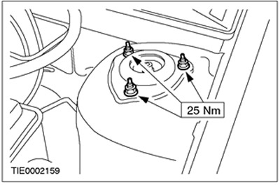
11. Install the engine support cushion.
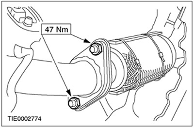
12.
NOTE: Use new nuts.
Connect the flexible connector to the exhaust system. Apply anti-seize lubricant to the studs.
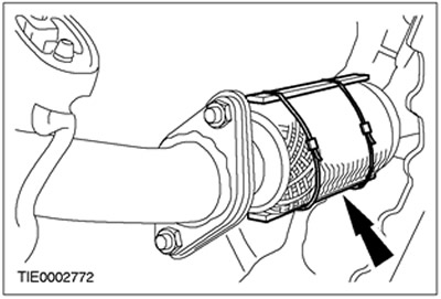
13. Remove the support bar from the flexible insert.
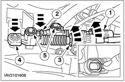
14. Connect the gear shift cables to the transaxle.
- 1. Loosen the support sleeve by turning it counterclockwise and install the gear selector cable into the bracket.
- 2.Connect the gear selector cable to the gear selector lever.
- 3. Loosen the support sleeve by turning it counterclockwise and install the gear shift cable.
- 4.Connect the gear shift cable to the shift lever.
- 5. Install the adjustment mechanism by pressing on the corresponding protrusions.
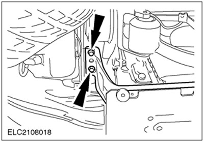
15. Install the radiator support bracket and radiator (left side shown).
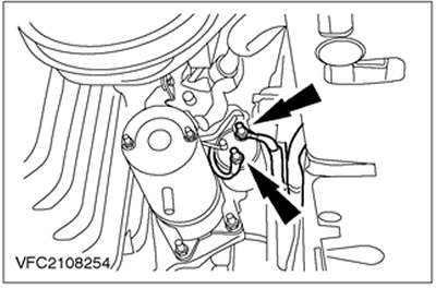
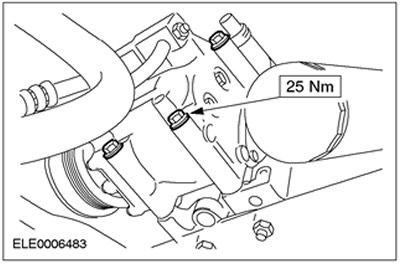
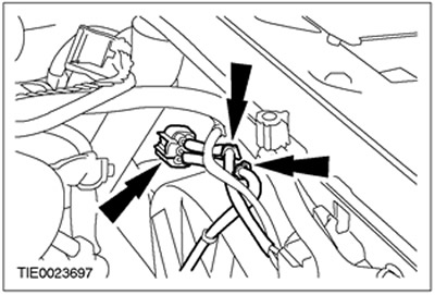
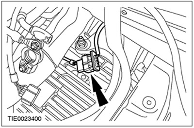
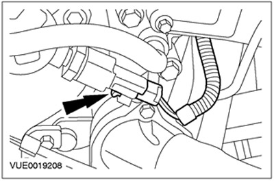
16. Connect the starter plug and connect the power cable.
17.
NOTE: Use a new nut.
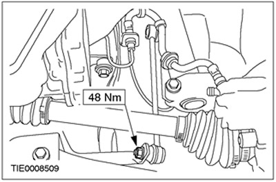
Connect the left tie rod end.
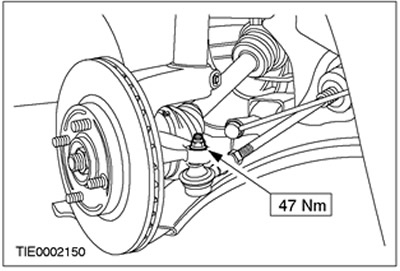
18.
CAUTION: Using a soft cloth, cover the ball joint seal.
Connect the lower control arms to the steering knuckles (left side shown).
19. Connect the vehicle's anti-roll bar on the left side.
20. Install the left front wheel and tire assembly. Refer to Section 204-04 for additional information.
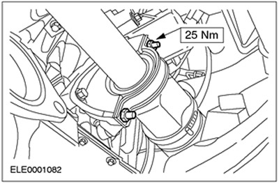
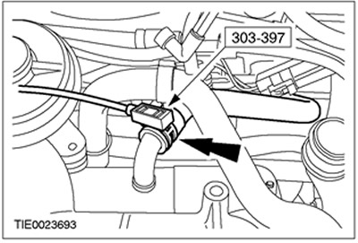
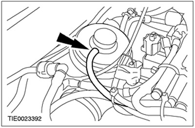
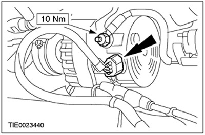
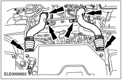
21. Using the special tool, connect the return hose to the power steering pump.
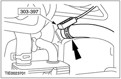
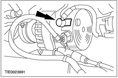
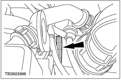
22. Using the special tool, connect the coolant hose to the oil cooler.
Cars with air conditioning system
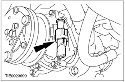
23. Connect the air conditioning compressor (four bolts).
24. Connect the air conditioning compressor plug connector and connect it to the air conditioning compressor.
All cars
25. Connect the horn plug and the horn wiring harness.
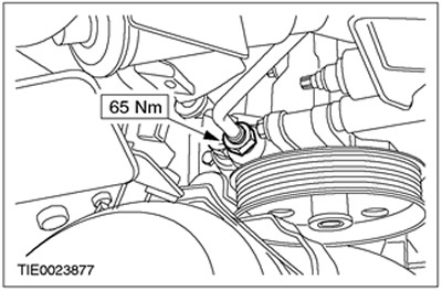
26. Install the accessory drive belt. Refer to Section 303-05 for additional information.
27. Lower the vehicle.
Cars equipped with air conditioning system
28. Disconnect the air conditioning system heat exchanger.
All cars
29. Connect the cooling fan electric connector and connect the cooling fan wiring harness to the cooling fan housing.
30. Install the expansion tank of the cooling system.
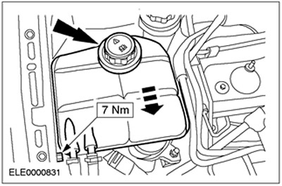
31. Using the special tool, connect the lower coolant hose to the expansion tank of the cooling system.
32. Connect the fuel supply and return line quick release couplings. Refer to Section 310-00 for additional information.
33. Connect the fuel supply and return lines to the appropriate bracket.
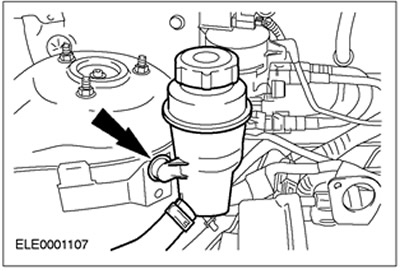
34. Secure the power steering fluid reservoir.
35. Connect the power steering high pressure line to the bracket.
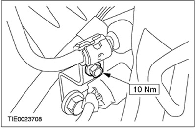
36. Connect the power steering high pressure line bracket to the lifting eye.
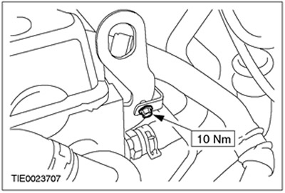
37. Connect the power steering high pressure line bracket to the timing belt cover stud.
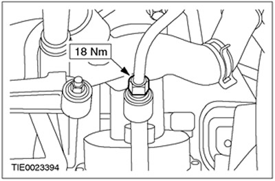
38. Connect the power steering high pressure line to the power steering pump.
Cars without common rail fuel injection
39. Disconnect the high pressure fuel pump connector.

40. Connect the vacuum hoses to the exhaust gas recirculation (EGR) valve and connect the corresponding plug connector.
Cars with EGR cooler
41. Using the special tool, connect the upper coolant hose to the EGR cooler.
Vehicles with common rail fuel injection system
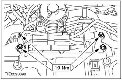
42. Connect the electronic vacuum control valve support bracket to the intake manifold.
43. Connect the EGR vacuum hose.
44. Connect the EGR vacuum hose to the EGR valve.
45. Connect the injector control module plug connector.
All cars
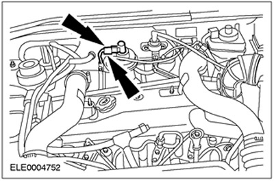
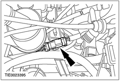
46. Connect the engine wiring harness.
47. Connect the vacuum hose to the vacuum diaphragm block.
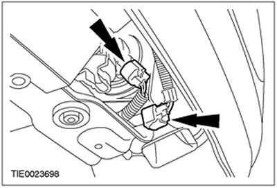
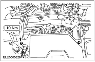
48. Connect the generator plug and connect the generator power wire.
49. Install the generator electrical connector cover.
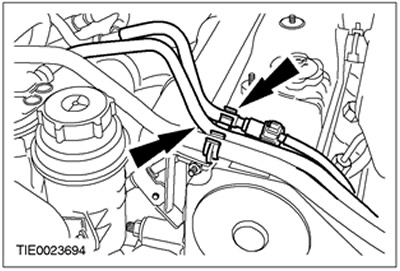
50. Using the special tool, connect the cooling system hoses to the thermostat housing and to the coolant distribution pipe.
Vehicles with common rail fuel injection system
51. Connect the high fuel pressure sensor connector.
All cars
52.
NOTE: Use a new gasket.
Install the thermostat housing.
53. Using the special tool, connect the upper coolant hose to the thermostat housing.
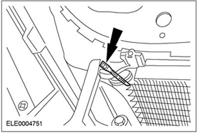
54. Connect the vacuum line to the brake booster vacuum pump.
55. Connect the oil level indicator dipstick.
56. Connect the glow plug wire terminal block.
57. Connect the glow plug power wire to the glow plug wire terminal block.
58. Install the air intake pipe.
59. Install the air cleaner outlet pipe.
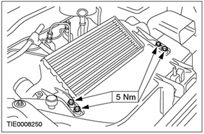
60. Install the charge air cooler.
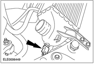
61. Connect the intake air temperature (IAT) sensor connector.
62. Install the charge air cooler duct.
63. Install the charge air cooler inlet and outlet pipes.
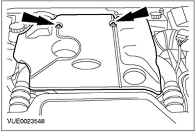
64. Install the top engine cover.
65. Tighten the nuts of the upper strut support assembly with the spring (on both sides).
66. Install the air cleaner. Refer to Section 303-12 for additional information.
67. Fill the cooling system with coolant and bleed the system. Refer to Section 303-03 for additional information.
68. Add power steering fluid and bleed the system. Refer to Section 211-00 for additional information.
69. Adjust the shift cables. Refer to Section 308-00 for additional information.
70. Install the battery tray and connect the battery. For additional information, refer to Section 414-01.