Special tool
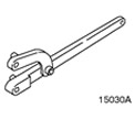 | Universal wrench for holding flanges 205-072 (15-030A) |
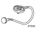 | Protractor for tightening bolts 303-174 (21-540) |
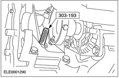
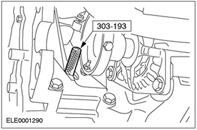
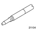 | Pin for setting the top dead center of the crankshaft 303-193 (21-104) |
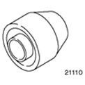 | Camshaft seal installer 303-199A (21-110A) |
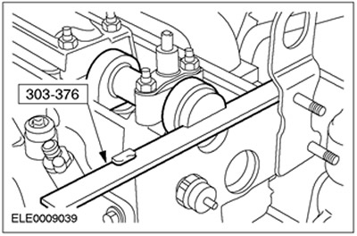
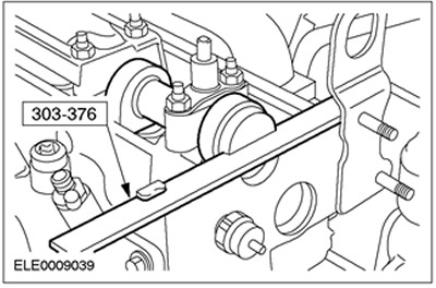
 | Camshaft alignment plate 303-376 (21-162V) |
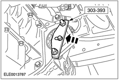
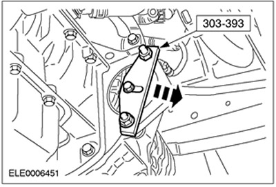
 | Flywheel locking tool 303-393 (21-168) |
 | Clamp remover/installer 303-397 (24-003) |
 | Stand 303-435 (21-187) |
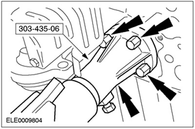
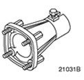 | Support bracket for 303-435 303-435-06 (21031B) |
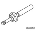 | Oil pump alignment tool 303-652 (21-230) |
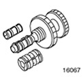 | Clutch disc alignment tool 308-204 (16-067) |
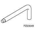 | Crankshaft Position Sensor Bracket Alignment Pin 310-057 (23-049) |
General equipment:
- Micrometer
- Probe set
- Internal micrometer
- Piston ring compressor
- Stand for dial indicator
- Dial indicator
- Measuring device for radial clearances in plain bearings «Plastigage»
| Name | Specification |
| sealant | WSE-M4G323-A4 |
| sealant | WSK-M2G348-A5 |
| Engine oil 5W-30 | WSS-M2C912-A1 |
All cars
CAUTION: Diesel fuel injection equipment is manufactured to very precise tolerances and very close clearances. Therefore, it is especially important to observe absolute cleanliness when working with these elements. Always insert plugs into any open holes or lines.
1. Coat the main journals, bearing shells and thrust washers with clean engine oil.
2.
CAUTION: Install the upper and lower main bearing shells in the correct order.
Install the main bearing shells to the cylinder block and main bearing caps.
3. Install the crankshaft in the cylinder block.
4.
NOTE: The grooves in the thrust washers must face outwards.
Install the crankshaft thrust washers into the third main bearing with the oil grooves facing out.
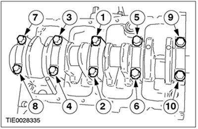
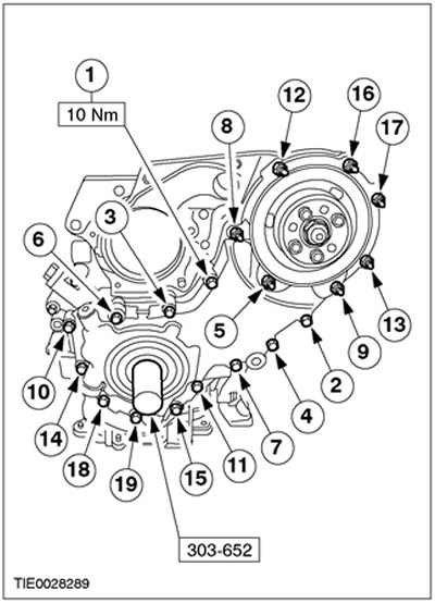
5.
NOTE: Install the main bearing caps with the arrows facing forward. The covers are labeled 1, 2, 3, 4 and 5 starting at the front and working towards the rear of the engine.
Install the crankshaft.
| Tighten the bolts working in the sequence shown in three steps. |
| Stage 1: Tighten bolts 1 to 10 to 45 Nm. |
| Stage 2: Tighten bolts 1 to 10 to 70 Nm. |
| Stage 3: Turn bolts 1 to 10 60 degrees. |
6. Apply clean engine oil to the running surfaces of the cylinders.
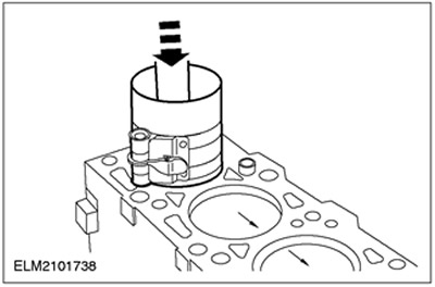
7.
NOTE: Install pistons with arrows facing front of engine.
NOTE: The joints of the piston rings and the oil scraper elements must be evenly spaced around the circumference.
Using an appropriate piston ring compressor, install the pistons. Install clean and dry connecting rod bearing shells into the connecting rods.
8.
CAUTION: Connecting rod bearing cap bolts should only be used twice.
NOTE: Mark the bolt heads with a center punch to indicate reuse.
NOTE: The connecting rod bearing cap markings must face the front of the engine.
Install the connecting rod bearing caps.
- Tighten the bolts in three steps.
- Stage 1: Tighten the bolts by hand.
- Stage 2: 25 Nm
- Stage 3: 65 Nm
- After installation, apply engine oil to the necks.
9.
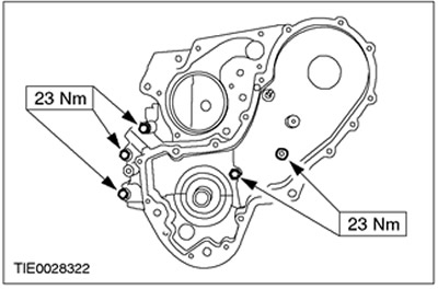
NOTE: Install a new timing chain rear case gasket.
Install the rear timing chain case.
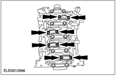
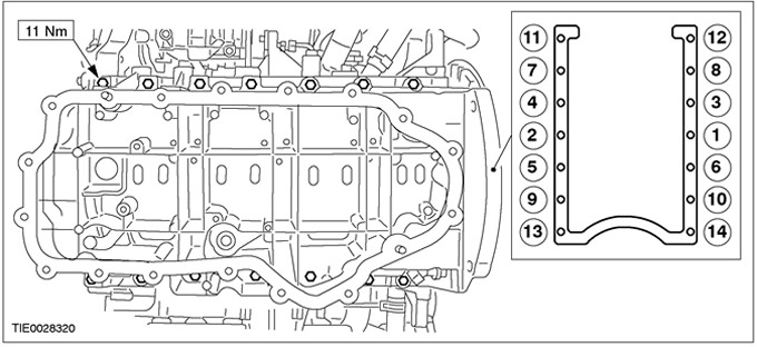
10.
NOTE: Install a new ladder frame gasket.Install ladder frame (14 bolts).
- Align the ladder frame flush with the cylinder block.
- Tighten the bolts in the sequence shown.
Vehicles with air conditioning
11. Install the air conditioning compressor support bracket (A/C).
All cars
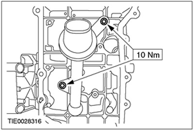
12.
NOTE: Install a new oil pump intake tube O-ring.
Install the oil pump intake pipe.
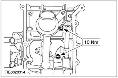
13.
NOTE: Install new O-rings.
Install the oil pump connecting pipe.
14.
NOTE: Do not damage mating surfaces.
NOTE: Mating surfaces and blind holes must be free of sealant and oil residue.
Clean the mating surfaces of the oil pan and ladder frame.
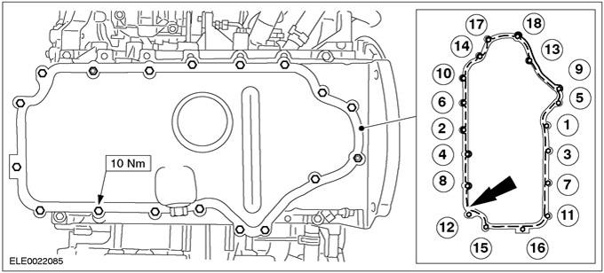
15.
CAUTION: Make sure the sealant does not get into the blind holes of the ladder frame. Failure to follow this instruction may result in engine damage.
NOTE: Install the oil sump within ten minutes of applying the sealant.
NOTE: Once the oil sump is in contact with the ladder frame, it should not be removed.
Install the oil pan.
- Apply a 2.5 mm bead of sealant to the ladder frame (dashed line).
- Tighten the bolts and nuts in the sequence shown.
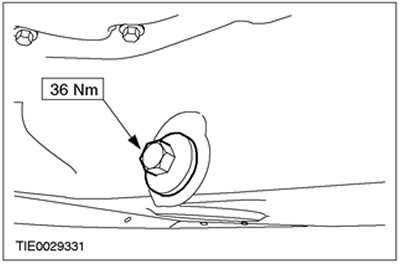
16.
NOTE: Inspect the oil sump drain plug seal for damage. Install a new drain plug and seal if necessary.
Install drain plug.
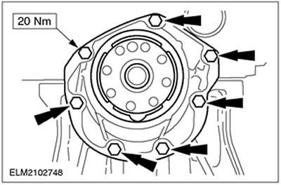
17.
NOTE: A new crankshaft rear oil seal carrier is shipped with a locating sleeve that must be removed during installation.
NOTE: Do not fully tighten the crankshaft rear oil seal retainer bolts at this stage.
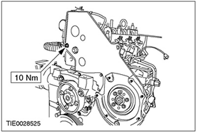
Install the crankshaft rear oil seal retainer.
18. Tighten the crankshaft rear oil seal retainer bolts.
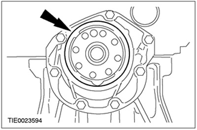
19. Remove the mounting sleeve of the crankshaft rear oil seal holder.
20.
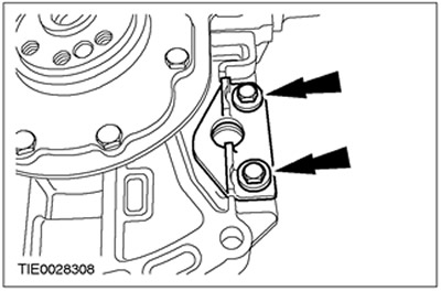
NOTE: Do not fully tighten the crankshaft position sensor support bracket bolts at this stage (CKP).
Install the CKP sensor support bracket.
21.
NOTE: Install new flywheel bolts.
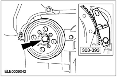
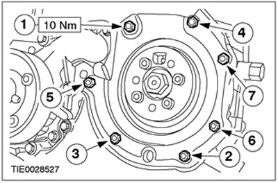
Using the special tool, install the flywheel.
- Tighten the bolts working in the sequence shown in three steps.
- Stage 1: 18 Nm
- Stage 2: 45 degrees
- Stage 3: 45 degrees
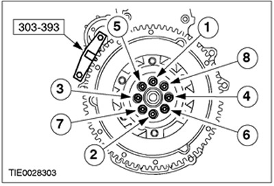
22. Remove the special tool.
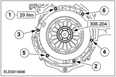
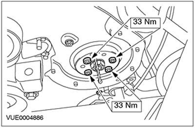
23. Using the special tool, center the clutch disc on the pressure plate.
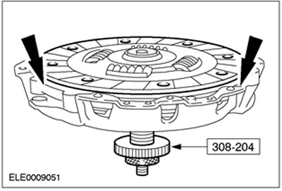
24.
CAUTION: Tighten the clutch pressure plate bolts by hand and then to the specified torque two turns at a time, working in the sequence shown.
Using the special tool, install the clutch disc and pressure plate. Remove the special tool.
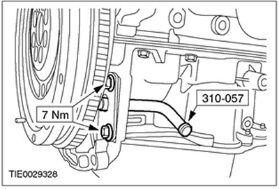
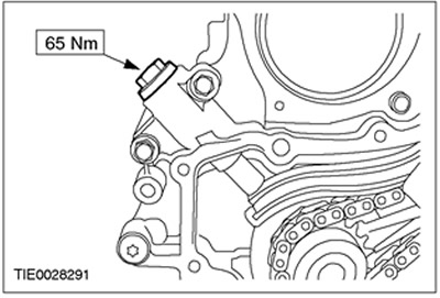
25. Using the special tool, install the CKP sensor mounting bracket.
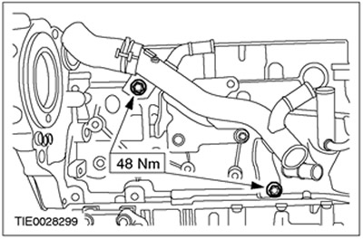
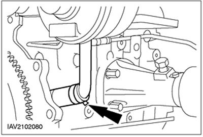
26. Install the coolant distribution pipe.
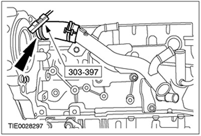
27. Using the special tool, connect the top coolant hose to the coolant distribution line.
28.
NOTE: Install a new high pressure fuel pump gasket.
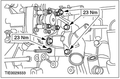
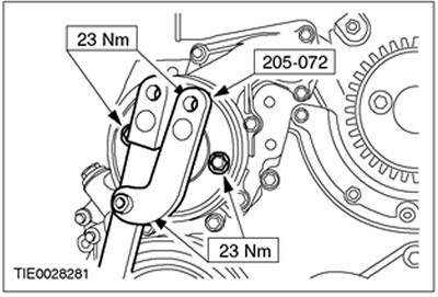
Install the high pressure fuel pump.
29. Install the high pressure fuel pump bracket.
30. Install the chain, sprockets and timing guides.
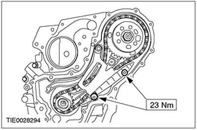
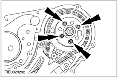
31.
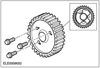
NOTE: Do not tighten the injection pump sprocket bolts at this stage.
Install the high pressure fuel pump sprocket.
32. Install the timing chain tensioner.
33. Using the special tool, install the timing chain housing cover.
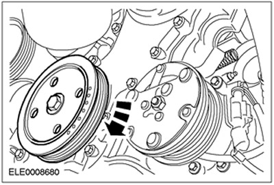
34. Install the accessory drive belt pulley.

35. Using the special tool, install the crankshaft pulley.
- Tighten the bolt, working in two steps.
- Stage 1: 90 Nm
- Stage 2: 90 degrees
36. Install the special tool. Remove the cylinder block cap.

37.
NOTE: Turn the crankshaft in the normal direction of rotation.
Rotate the crankshaft to top dead center (w.m.t.). Slowly turn the crankshaft until it stops.
38.
NOTE: Using a 6 mm drill, set the high pressure fuel pump to crankshaft top dead center.
Install the high pressure fuel pump sprocket.
39. Remove the special tool.

40.
NOTE: Turn the crankshaft in the normal direction of rotation.
NOTE: Using an appropriate marker, mark the crankshaft pulley to indicate top dead center.
Rotate the crankshaft 90 degrees.

41.
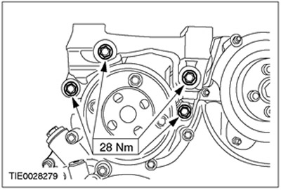
NOTE: Install a new water pump gasket.
Install the water pump.
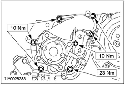
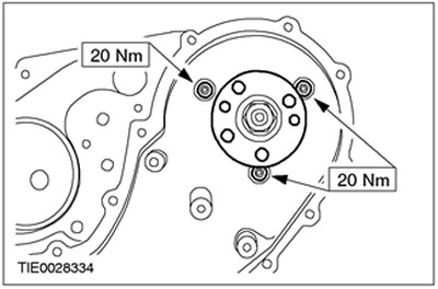
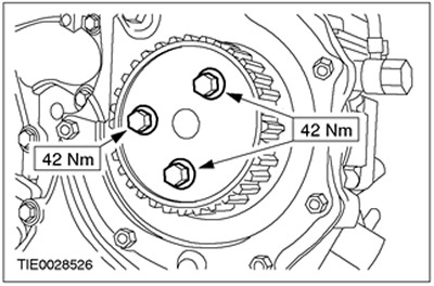
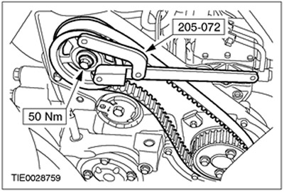
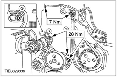
42. Using the special tool, install the water pump pulley.
43.
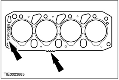
CAUTION: The thickness of the new cylinder head gasket must match the thickness of the «old» (hole/prong markings).
NOTE: Marking «TOP/OBEN» («Up»).
Install a new cylinder head gasket.
44.
NOTE: The turbocharger oil return hose must be connected when the cylinder head is installed.
Install the cylinder head.
45.
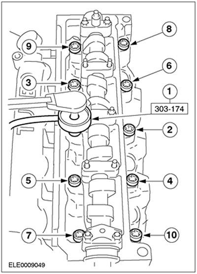
CAUTION: Install new cylinder head bolts.
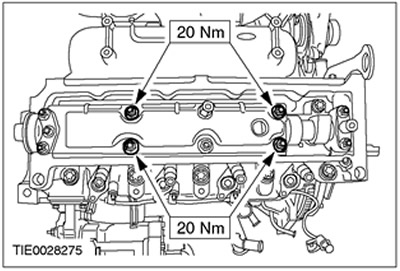
Install the cylinder head bolts.
- Using the special tool, tighten the bolts in four steps in the sequence shown.
- Stage 1: Tighten bolts 1 to 10 to 20 Nm.
- Stage 2: Tighten bolts 1 to 10 to 54 Nm.
- Stage 3: Turn bolts 1 to 10 90 degrees.
- Stage 4: Short bolts: 70 degrees, long bolts: 90 degrees.
46. Install the oil separator.
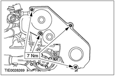
47. Install the rear timing belt cover.
48.
NOTE: Install a new high pressure fuel pump oil seal retainer.
Install the high pressure fuel pump oil seal retainer.
49. Using sealant, seal the high pressure fuel pump pulley against the fuel pump sprocket. Apply sealant to the outer edge of the injection pump pulley bolt holes.
50. Install the high pressure fuel pump pulley.
51.
NOTE: Do not fully tighten the camshaft pulley bolt at this stage.
Install the camshaft pulley bolt.
52. Install the special tool.

53. Install the special tool.
54.
NOTE: Turn the crankshaft in the normal direction of rotation.
Rotate the crankshaft to top dead center (w.m.t.). Slowly turn the crankshaft until it stops.
55.
CAUTION: Do not rotate the crankshaft while installing the special tool.
CAUTION: Make sure the crankshaft is at top dead center before locking the special tool.
CAUTION: Be sure to install the special tool correctly.
Using the special tool, lock the crankshaft in the desired position.
56.
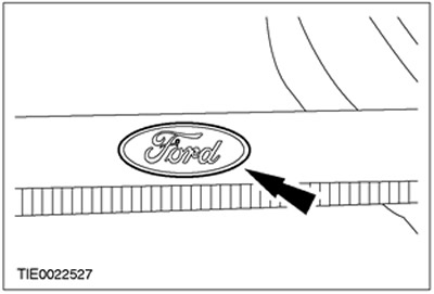
NOTE: Use only the latest timing belts. They can be recognized by the laser engraved Ford logo.
Check the timing belt.
Engines with mechanical timing belt tensioner
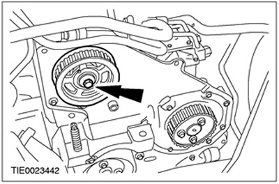
57. Install a new automatic timing belt tensioner.
All cars
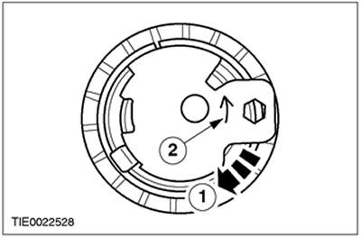
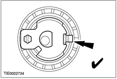
58. Check the timing belt tensioner.
- 1.Check that the tensioner pointer turns freely clockwise.
- 2. The arrow shows the counterclockwise rotation of the tensioner.
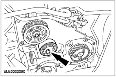
59. Turn the timing belt tensioner adjustment lever clockwise to the position «3 hours».
60.
NOTE: Do not fully tighten the timing belt tensioner mounting bolt at this stage.
Install the timing belt tensioner.
61.
CAUTION: Never install a used timing belt.
CAUTION: Install the timing belt so that the arrows point in the direction of rotation of the crankshaft.
NOTE: Install a new timing belt.
Put on the timing belt.
62.
NOTE: The camshaft pulley must be able to rotate freely on the camshaft cone.
Tighten the camshaft pulley bolt by hand and then loosen it by half a turn.
63.
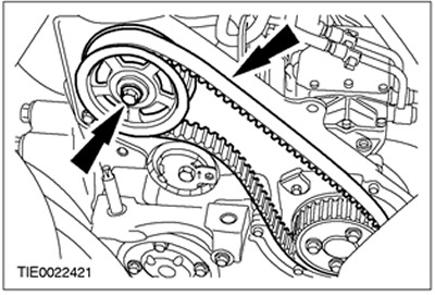
NOTE: Using a socket wrench, maintain tension on the timing belt until the timing belt tensioner bolt is tightened.
Tension the timing belt.
- 1.Turn the timing belt tensioner adjustment lever counterclockwise to tighten the timing belt slightly.
- 2. The pointer should be between the edges of the window.
- 3. Tighten the timing belt tensioner mounting bolt.
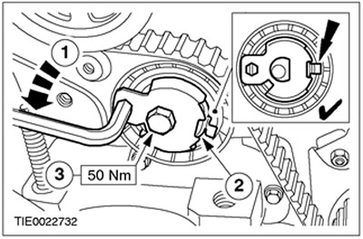
64. Using the special tool, tighten the camshaft pulley bolt.
65. Remove the special tool.
66. Remove the special tool.
67. Remove the special tool.

68.
NOTE: Turn the crankshaft in the normal direction of rotation.
Rotate the crankshaft six turns.
69. Install the special tool.
70.
NOTE: Turn the crankshaft in the normal direction of rotation.
Rotate the crankshaft to top dead center. Slowly turn the crankshaft until it stops.
71.
CAUTION: Do not rotate the crankshaft while installing the special tool.
CAUTION: Make sure the crankshaft is at top dead center before locking the special tool.
CAUTION: Be sure to install the special tool correctly.
Using the special tool, lock the crankshaft in the desired position.

72.
CAUTION: If the pointer is not visible in the timing belt tensioner window, repeat the timing belt tensioning procedure.
Check if the timing belt tensioner pointer is in the window.
73.
CAUTION: If the special tool cannot be installed, the timing belt tensioning procedure must be repeated.
Install the special tool. If the special tool cannot be installed, the procedure must be repeated.
Vehicles with an aftercooler.
74. Install the front engine mount bracket.
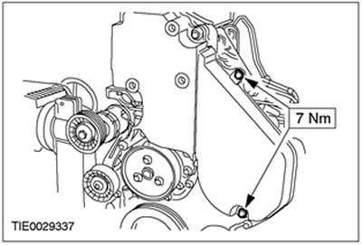
75. Install the timing belt cover.
Vehicles without aftercooler
76. Install the front engine mount bracket.
77. Install the lower timing belt cover.
All cars
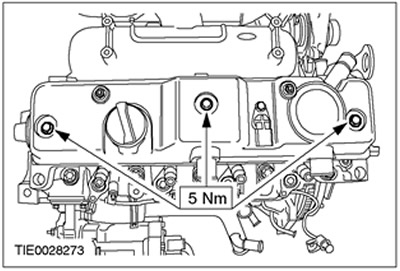
78.
NOTE: Install a new valve cover gasket if necessary.
Install the valve cover.
- 1. Apply engine oil to the valve cover gasket before installing it.
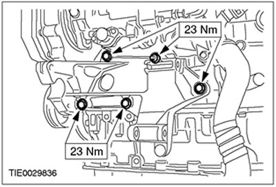
79. Install the generator bracket.
80.
NOTE: Install a new oil cooler gasket.
Install the oil cooler.

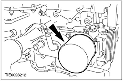
81.
NOTE: Install a new oil filter.
Install the oil filter.
82.
NOTE: Install new turbocharger oil supply line o-rings.
Install the turbocharger oil supply line.
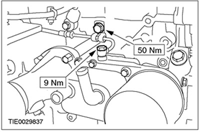
83.
NOTE: Install a new turbocharger oil supply line O-ring.
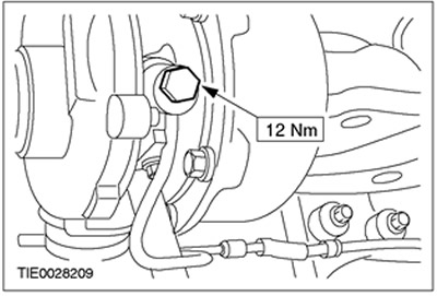
Connect the oil supply line to the turbocharger.
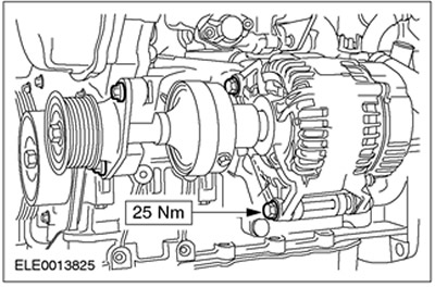
84. Install the generator and drive shaft.
85.
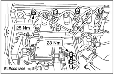
NOTE: Install new high pressure fuel feed lines.
Install high pressure fuel lines.
86.
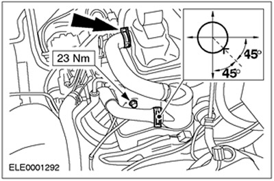
NOTE: Connect the oil separator to the engine lift eye. Tighten the engine lift lug and then tighten the oil separator.
NOTE: Install the clamp at a 45 degree angle to the horizontal.
Install the crankcase ventilation oil separator.
87. Fill the engine with engine oil.
88. Remove the special tool.
Visitor comments