Special tool
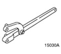 | Universal wrench for holding flanges 205-072 (15-030A) |
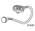 | Protractor for tightening bolts 303-174 (21-540) |
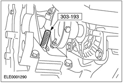
 | Pin for setting the top dead center of the crankshaft 303-193 (21-104) |
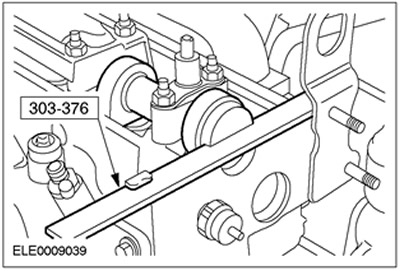
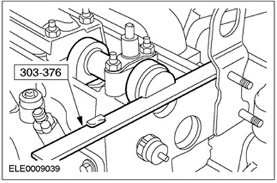
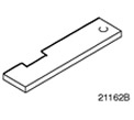 | Camshaft alignment plate 303-376 (21-162V) |
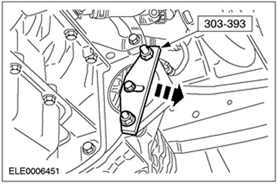
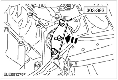
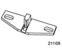 | Flywheel locking tool 303-393 (21-168) |
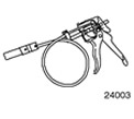 | Clamp remover/installer 303-397 (24-003) |
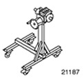 | Stand 303-435 (21-187) |
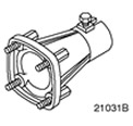 | Support bracket for 303-435 303-435-06 (21-031V) |
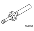 | Oil pump alignment tool 303-652 (21-230) |
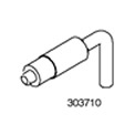 | Crankshaft Alignment Tool 303-710 (21-257) |
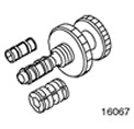 | Clutch disc alignment tool 308-204 (16-067) |
General equipment:
- Micrometer
- Probe set
- Internal micrometer
- Piston ring compressor
- Stand for dial indicator
- Dial indicator
- Measuring device for radial clearances in plain bearings "Plastigage"
- Vacuum cleaner for engine
| Name | Specification |
| Silicone sealant and sealant | WSE-M4G323-A4 |
| sealant | WSK-M2G348-A5 |
| Engine oil 5W-30 | WSS-M2C912-A1 |
CAUTION: Diesel fuel injection equipment is manufactured to very precise tolerances and very close clearances. Therefore, it is especially important to observe absolute cleanliness when working with these elements. Always insert plugs into any open holes or lines.
CAUTION: Do not disassemble fuel injectors or clean their nozzles, even with ultrasonication.
CAUTION: To prevent foreign material from entering fuel injection system components, always clean before making any repairs to such components.
1. Coat the main journals, bearing shells and thrust washers with clean engine oil.
2. Install the main bearing shells in the cylinder block and main bearing caps.
3. Install the crankshaft in the cylinder block.
4.
NOTE: The grooves in the thrust washers must face outwards.
Install the crankshaft thrust washers into the third main bearing with the oil grooves facing out.
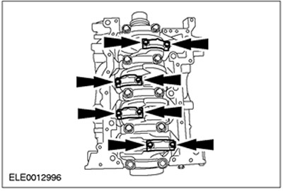
5.
NOTE: Install the main bearing caps with the arrows facing forward. The covers are labeled 1, 2, 3, 4 and 5 starting at the front and working towards the rear of the engine.
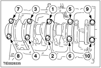
Install the crankshaft.
- Tighten the bolts working in the sequence shown in three stages.
- Stage 1: Tighten bolts 1 to 10 to 45 Nm.
- Stage 2: Tighten bolts 1 to 10 to 70 Nm.
- Stage 3: Turn bolts 1 to 10 60 degrees.
6. Apply clean engine oil to the running surfaces of the cylinders.
7.
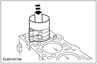
NOTE: Install pistons with arrows facing front of engine.
NOTE: The joints of the piston rings and the oil scraper elements must be evenly spaced around the circumference.
Using an appropriate piston ring compressor, install the pistons. Install clean and dry connecting rod bearing shells into the connecting rods.
8.
CAUTION: Connecting rod bearing cap bolts should only be used twice.
NOTE: Mark the bolt heads with a center punch to indicate reuse.
NOTE: The connecting rod bearing cap markings must face the front of the engine.
Using the special tool, install the connecting rod bearing caps.
- Tighten the bolts in three steps.
- Stage 1: Tighten the bolts by hand.
- Stage 2: 60 degrees
- Stage 3: 20 degrees
- After installation, apply engine oil to the necks.
9.
NOTE: Install a new timing chain rear case gasket.
Install the rear timing chain case.
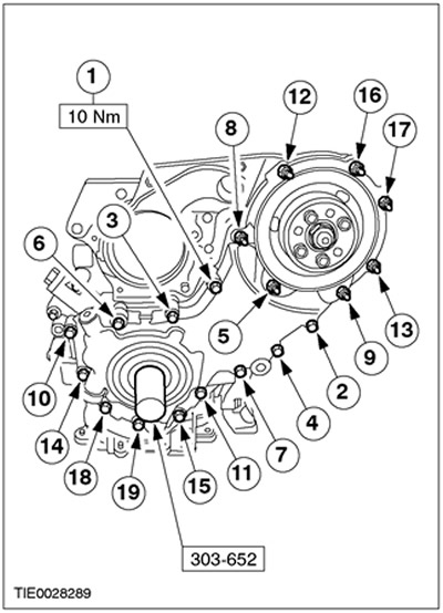
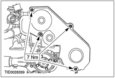
10. NOTE: Install a new ladder frame gasket.
Install ladder frame (14 bolts).
- Align the ladder frame flush with the cylinder block.
- Tighten the bolts in the sequence shown.
11. Install the air conditioning compressor support bracket (A/C).
12.
NOTE: Install a new oil pump intake tube O-ring.
Install the oil pump intake pipe.
13.
NOTE: Install new O-rings.
Install the oil pump connecting pipe.
14.
NOTE: A new crankshaft rear oil seal carrier is shipped with a locating sleeve that must be removed during installation.
NOTE: Do not fully tighten the crankshaft rear oil seal retainer bolts at this stage.
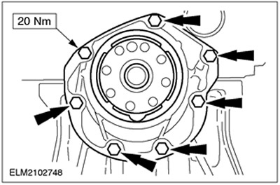
Install the crankshaft rear oil seal retainer.
15. Tighten the crankshaft rear oil seal retainer bolts.
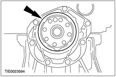
16. Remove the crankshaft rear oil seal holder locating sleeve.
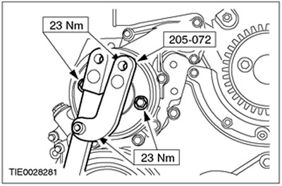
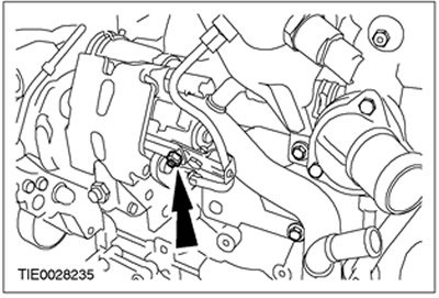
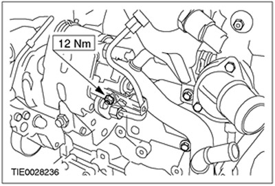
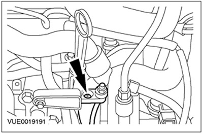
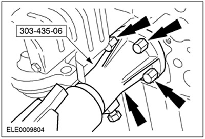
17. Using the special tool, install the crankshaft position sensor support bracket (CKP).
18.
CAUTION: Ladder frame blind holes must be free of sealant residue. Failure to follow this instruction may result in engine damage.
NOTE: Do not damage mating surfaces.
NOTE: Mating surfaces and blind holes must be free of sealant and oil residue.
Clean the mating surfaces of the oil pan and ladder frame.
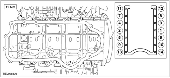
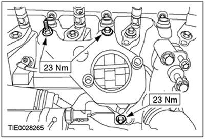
19.
NOTE: Install the oil sump within ten minutes of applying the sealant.
NOTE: Once the oil sump is in contact with the ladder frame, it should not be removed.
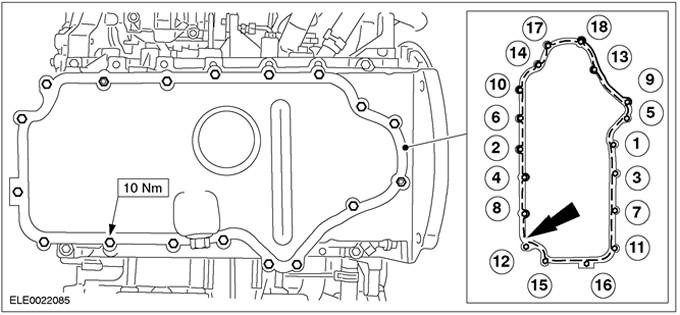
Install the oil pan.
- Apply a 2.5 mm bead of silicone sealant and sealant to the ladder frame (intermittently).
- Tighten the bolts and nuts in the sequence shown.
20.
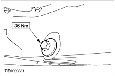
NOTE: Inspect the oil sump drain plug seal for damage. Install a new drain plug and seal if necessary.
Install drain plug.
21.
NOTE: Install new flywheel bolts.
NOTE: Do not fully tighten the flywheel bolts at this stage.
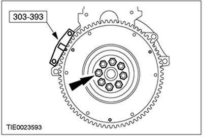
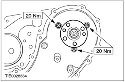
Install the dual flywheel.
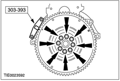
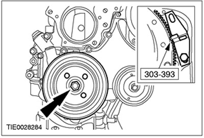
22. Using the special tool, lock the dual handwheel in position.
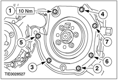
23.
NOTE: Install new flywheel bolts.
NOTE: Do not fully tighten the flywheel bolts at this stage.
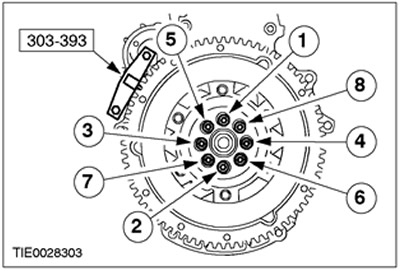
Using the special tools, install the dual flywheel.
- Tighten the bolts working in two steps in the sequence shown.
- Stage 1: 35 Nm
- Stage 2: 45 degrees
24. Remove special tools.
25. Inspect the dual flywheel. See Section 303-00 for more information.
26. Using the special tool, center the clutch disc on the pressure plate.
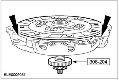
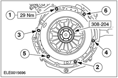
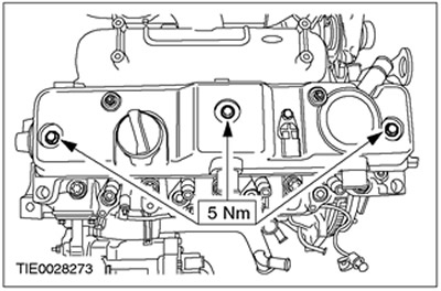
27.
CAUTION: Tighten the clutch pressure plate bolts by hand and then to the specified torque two turns at a time, working in the sequence shown.
Using the special tool, install the clutch disc and pressure plate.
28.
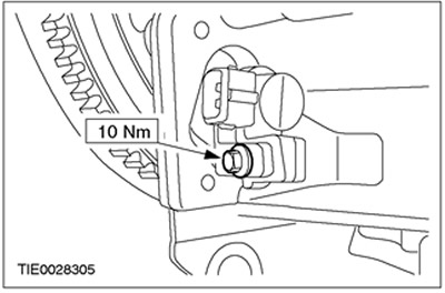
NOTE: Install a new crankshaft position sensor (CKP).
NOTE: The CKP sensor must make contact with the flywheel.
Install the CKP sensor.
29. Install the fuel pump bracket.
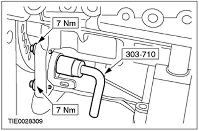
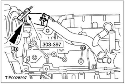
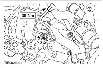
30. Install the coolant distribution pipe.
31. Using the special tool, connect the upper coolant hose to the coolant distribution pipe.
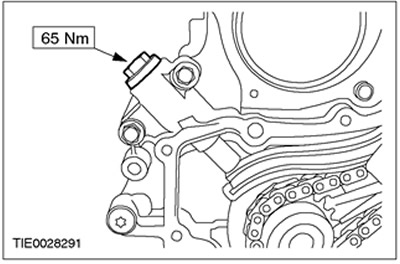
32.
NOTE: Install a new fuel pump gasket.
Install the fuel pump.
33. Install the fuel pump bracket.

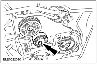
34. Install the chain, sprockets and timing guides.
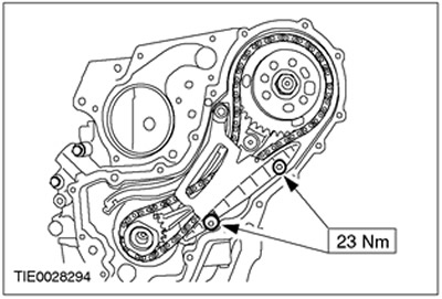
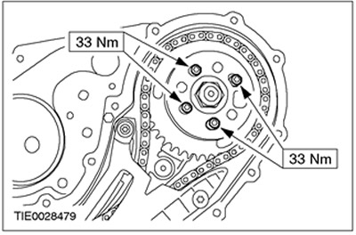
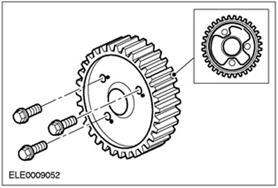
35. Install the fuel pump sprocket.
36. Install the timing chain tensioner.
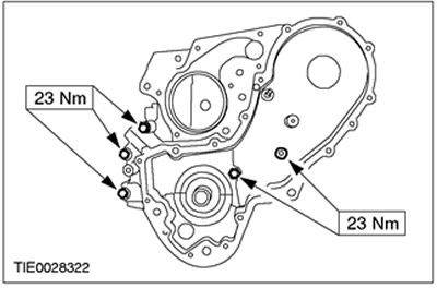
37.
NOTE: Install a new timing chain case cover gasket.
Using the special tool, install the timing chain housing cover.
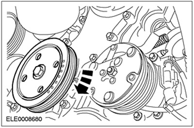
38. Install the accessory drive belt pulley.
39.
NOTE: Install a new crankshaft pulley bolt.
Using the special tool, install the crankshaft pulley.
- Tighten the bolt, working in two steps.
- Stage 1: 110 Nm
- Stage 2: 255 Nm
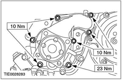
40.
NOTE: Install a new water pump gasket.
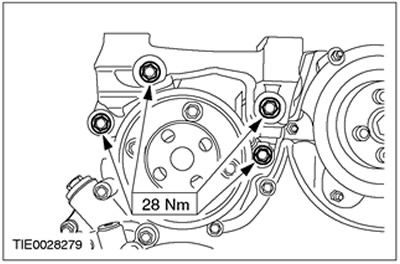
Install the water pump.
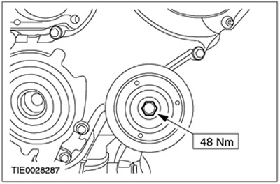
41. Using the special tool, install the water pump pulley.
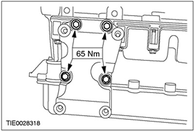
42. Install the front engine mount bracket.
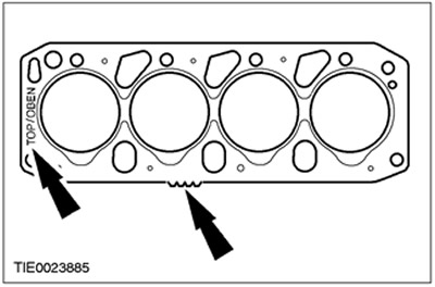
43.
CAUTION: The thickness of the new cylinder head gasket must match the thickness of the "old" (hole/prong markings).
NOTE: Marking "TOP/OBEN" ("Up").
NOTE: Install a new cylinder head gasket.
Install the cylinder head gasket.
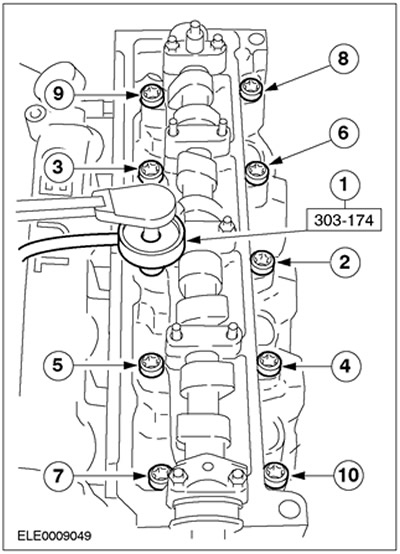
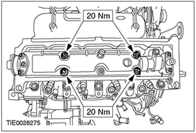
44.
CAUTION: Install new cylinder head bolts.
Install the cylinder head bolts.
- Using the special tool, tighten the bolts in four steps in the sequence shown.
- Stage 1: Tighten bolts 1 to 10 to 20 Nm.
- Stage 2: Tighten bolts 1 to 10 to 54 Nm.
- Stage 3: Turn bolts 1 to 10 90 degrees.
- Stage 4: Short bolts: 70 degrees, long bolts: 90 degrees.
45. Install the oil separator.
46. Install the rear timing belt cover.
47.
NOTE: Install a new high pressure fuel pump oil seal retainer.
Install the high pressure fuel pump oil seal retainer.
48. Using sealant, seal the high pressure fuel pump pulley against the high pressure fuel pump sprocket. Apply sealant to the outer edge of the injection pump pulley bolt holes.
49. Install the fuel pump pulley.
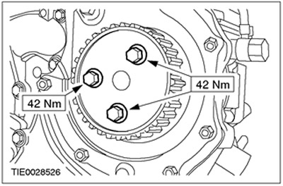
50.
NOTE: Do not fully tighten the camshaft pulley bolt at this stage.
Install the camshaft pulley bolt.
51. Install the special tool.

52. Install the special tool. Remove the plug from the cylinder block.

53.
NOTE: The crankshaft must be rotated in the direction of normal engine rotation.
Rotate the crankshaft to top dead center. Slowly turn the crankshaft until it stops.
54.
CAUTION: Be careful not to rotate the engine when installing the special tool.
CAUTION: Make sure the engine is at top dead center before installing the special tool.
CAUTION: Be sure to install the special tool correctly.
Using the special tool, block the engine in the required position.

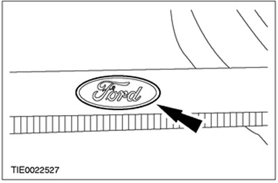
55.
NOTE: Use only the latest timing belts. They can be recognized by the laser engraved Ford logo.
Check the timing belt.
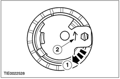
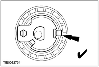
56. Check the timing belt tensioner.
- 1.Check that the tensioner pointer turns freely clockwise.
- 2. The arrow shows the counterclockwise rotation of the tensioner.
57. Turn the timing belt tensioner adjustment lever clockwise to the position "3 hours".
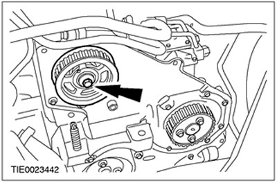
58.
NOTE: Do not fully tighten the timing belt tensioner mounting bolt at this stage.
Install the timing belt tensioner.
59.
CAUTION: Never install a used timing belt.
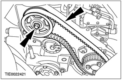
CAUTION: Install the timing belt so that the arrows point in the direction of engine rotation.
NOTE: Install a new timing belt.
Put on the timing belt.
60.
NOTE: The camshaft pulley must be able to rotate freely on the camshaft cone.
Tighten the camshaft pulley bolt by hand and then loosen it by half a turn.
61.
NOTE: Using a socket wrench, maintain tension on the timing belt until the timing belt tensioner bolt is tightened.
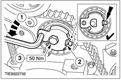
Tension the timing belt.
- 1.Turn the timing belt tensioner adjustment lever counterclockwise to tighten the timing belt slightly.
- 2. The pointer should be between the edges of the window.
- 3. Tighten the timing belt tensioner mounting bolt.
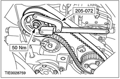
62. Using the special tool, tighten the camshaft pulley bolt.
- 1.Install the special tool.
- 2.Tighten the bolt.
63. Remove the special tool.
64. Raise and support the vehicle. Refer to Section 100-02 for more information.
65. Remove the special tool.
66. Remove the special tool.
67.
NOTE: The engine should only be turned in the normal direction of rotation of the crankshaft.
NOTE: Using a suitable marker, mark the crankshaft pulley to indicate top dead center.
Turn the engine over six revolutions.
68. Install the special tool.

69.
NOTE: The engine should only be turned in the normal direction of rotation of the crankshaft.
Rotate the engine to top dead center. Rotate the engine slowly until the crankshaft stops.
70.
CAUTION: Be careful not to rotate the engine when installing the special tool.
CAUTION: Before installing the lockout tool, make sure the engine is at top dead center.
CAUTION: Be sure to install the special tool correctly.
Using the special tool, block the engine in the required position.
71. Lower the car.
72.
CAUTION: If the pointer is not visible in the timing belt tensioner window, repeat the timing belt tensioning procedure.
Check if the timing belt tensioner pointer is in the window.
73.
CAUTION: If the special tool cannot be installed, the timing belt tensioning procedure must be repeated.
Install the special tool. If the special tool cannot be installed, the procedure must be repeated.
74.
NOTE: Install a new cylinder head cover gasket if necessary.
Install the cylinder head cover.
75. Install the timing belt cover.
76. Install the fuel manifold support bracket.
77.
NOTE: Do not tighten the fuel manifold mounting bolts at this stage.
Install the fuel manifold.
78.
NOTE: Install new high pressure fuel feed lines.
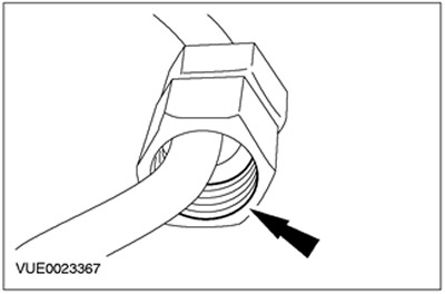
Lubricate the threads of the high pressure fuel supply line connections with clean ISO 4113 grease supplied in the high pressure fuel supply line spare parts kit.

79.
CAUTION: Do not allow the mating ends of the high pressure fuel supply line pin to strike as this may damage the fuel line and allow foreign material to enter the fuel injection system.
CAUTION: Remove the plugs from the high pressure fuel supply line, fuel injector and fuel manifold as soon as possible. Failure to follow this instruction may result in dirt entering the fuel injection system.
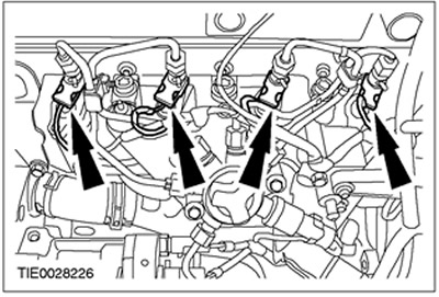
NOTE: To help identify the high pressure fuel supply lines, the fuel injector side connections are engraved with the cylinder number.
NOTE: Do not tighten the high pressure fuel feed nipple connections at this stage.
NOTE: Apply pressure to the high pressure fuel supply line to keep the nipple in contact with the fuel rail cone when connecting the nipple connection.
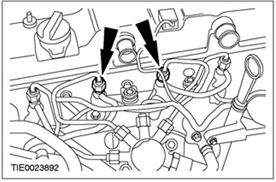
Connect the high pressure fuel lines to the fuel injectors. Discard plugs as they are no longer needed.
80.
CAUTION: Do not knock on the sealing surfaces of the high pressure fuel supply nipple connections, because this can damage the ends of the fuel line and allow foreign material to enter the fuel injection system.
CAUTION: Remove the plugs from the high pressure fuel supply line, fuel injector and fuel manifold as soon as possible. Failure to follow this instruction may result in dirt entering the fuel injection system.
NOTE: Do not tighten the high pressure fuel feed nipple connections at this stage.
NOTE: Apply pressure to the high pressure fuel supply line to keep the nipple in contact with the fuel rail cone when connecting the nipple connection.
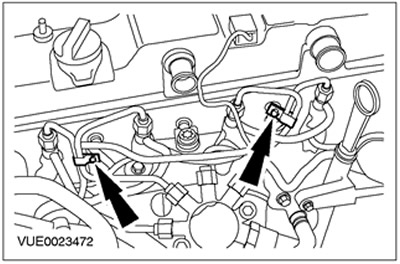
Connect the No. 1 and No. 4 cylinder feed lines to the fuel manifold. Discard plugs as they are no longer needed.
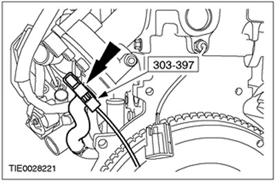
81.
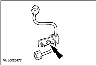
NOTE: Be sure to install the clip in the same position it was in before removal.
Install the clamp on the high pressure fuel supply line.
82.
NOTE: Install a new high pressure fuel supply pipe nipple.
Lubricate the threads of the high pressure fuel supply line connections with clean ISO 4113 grease supplied in the high pressure fuel supply line spare parts kit.
83.
CAUTION: Do not knock on the sealing surfaces of the high pressure fuel supply nipple connections, because this can damage the ends of the fuel line and allow foreign material to enter the fuel injection system.
CAUTION: Remove the plugs from the high pressure fuel supply line, fuel injector and fuel manifold as soon as possible. Failure to follow this instruction may result in dirt entering the fuel injection system.
NOTE: Do not tighten the high pressure fuel supply pipe nipple at this stage.
NOTE: Apply pressure to the high pressure fuel supply line to keep the nipple in contact with the fuel pump cone and fuel manifold when connecting the nipple connections.
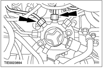
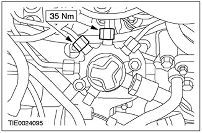
Install the high pressure fuel supply line.
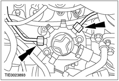
- 1. Connect the high pressure fuel supply line to the fuel manifold.
- 2. Connect the high pressure fuel supply line to the fuel pump.
- Discard plugs as they are no longer needed.
84.
CAUTION: Do not allow the mating ends of the high pressure fuel supply line pin to strike as this may damage the fuel line and allow foreign material to enter the fuel injection system.
CAUTION: Remove the plugs from the high pressure fuel supply line, fuel injector and fuel manifold as soon as possible. Failure to follow this instruction may result in dirt entering the fuel injection system.
NOTE: To help identify the high pressure fuel supply lines, the fuel injector side connections are engraved with the cylinder number.
NOTE: Do not tighten the high pressure fuel feed nipple connections at this stage.
NOTE: Apply pressure to the high pressure fuel supply line to keep the nipple in contact with the fuel injector cones when connecting the nipple connections.
Connect the high pressure fuel lines to the fuel injectors.
85.
CAUTION: Do not knock on the working surfaces of the sealing elements of the nipple connections of the high pressure fuel supply lines, because. this can damage the ends of the fuel lines and allow foreign material to enter the fuel injection system.
CAUTION: Remove the plugs from the high pressure fuel supply line, fuel injector and fuel manifold as soon as possible. Failure to follow this instruction may result in dirt entering the fuel injection system.
NOTE: Do not tighten the high pressure fuel feed nipple connections at this stage.
NOTE: Apply pressure to the high pressure fuel supply line to keep the nipple in contact with the fuel manifold cone when connecting the nipple connections.
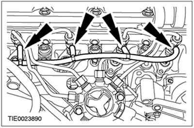
Connect the high pressure fuel supply lines of cylinders 2 and 3 to the fuel manifold. Discard plugs as they are no longer needed.
86. Connect the fuel injector return line to the fuel injectors.
87.
NOTE: Do not tighten the high pressure fuel supply line clamps at this stage.
NOTE: Clips should be reinstalled in the same position from which they were removed.
Install the high pressure fuel supply line clamps.
88.
NOTE: Do not fully tighten the high pressure fuel line clamp retaining nut at this stage.
Install the high pressure fuel line clamp nut.
89. Tighten the fuel rail mounting bolts.
90.
CAUTION: The high pressure fuel supply nipple tightening tool should be installed at the top of the connection as this is where most of the material is found. Failure to follow this instruction may result in damage to the pin connection.
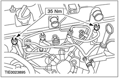
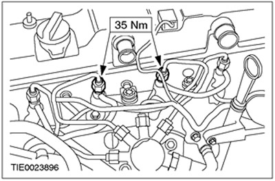
Tighten the nipple connections of the fuel supply lines of cylinders Nos. 1 and 4 on the fuel injectors.
91.
CAUTION: The high pressure fuel supply nipple tightening tool should be installed at the top of the connection as this is where most of the material is found. Failure to follow this instruction may result in damage to the pin connection.
Tighten the nipple connections of the No. 1 and No. 4 cylinder fuel supply lines on the fuel manifold.
92.
CAUTION: The high pressure fuel supply nipple tightening tool should be installed at the top of the connection as this is where most of the material is found. Failure to follow this instruction may result in damage to the pin connection.
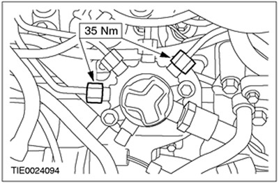
Tighten the nipple connections of the high pressure fuel supply lines.
93.
CAUTION: The high pressure fuel supply nipple tightening tool should be installed at the top of the connection as this is where most of the material is found. Failure to follow this instruction may result in damage to the pin connection.
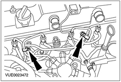
Tighten the nipple connections of the fuel supply lines of cylinders Nos. 2 and 3 on the fuel injectors.
94.
CAUTION: The high pressure fuel supply nipple tightening tool should be installed at the top of the connection as this is where most of the material is found. Failure to follow this instruction may result in damage to the pin connection.
Tighten the nipple connections of the Nos. 2 and 3 cylinder fuel supply lines on the fuel manifold.
95.
NOTE: Clips should be reinstalled in the same position from which they were removed.
Tighten the high pressure fuel supply line clamps.
96.
CAUTION: Close the high pressure fuel pump opening to prevent dirt from entering it.
Tighten the high pressure fuel line clamp nut.
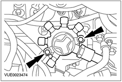
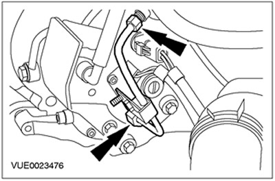
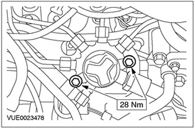
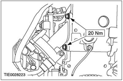
97. Connect the high pressure fuel pump connectors.
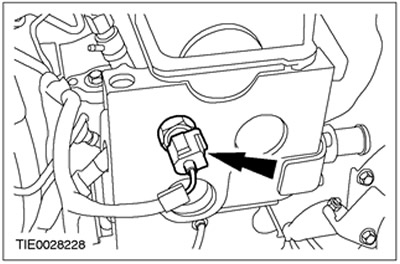
98. Connect the high fuel pressure sensor connector.
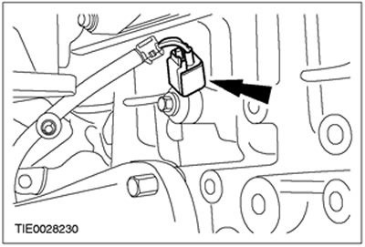
99. Dock the plug connector of the knock sensor (KS).
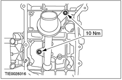
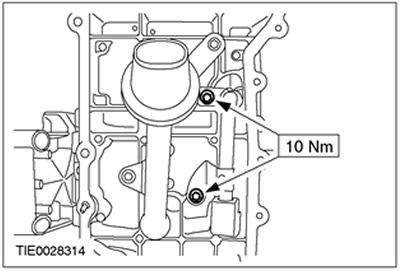
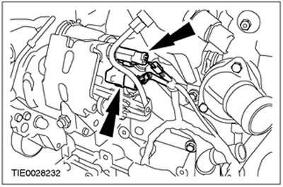
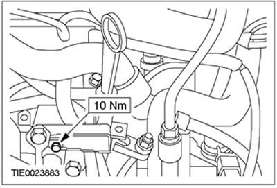
100. Connect the glow plug harness bracket to the oil dipstick tube bracket.
101. Connect the oil dipstick tube bracket to the thermostat housing.
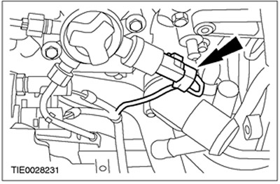
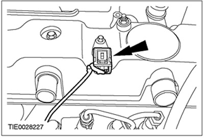
102. Connect the plug connector of the oil pressure switch.
103. Dock the plug connector of the camshaft position sensor (CMP).
104. Dock the plug connectors of the fuel injectors.
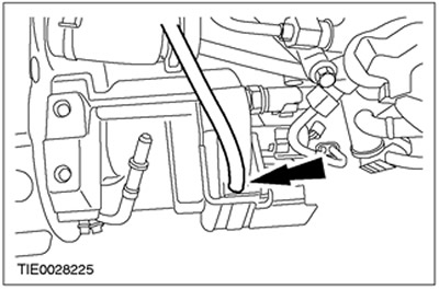
105. Connect the fuel injector return line to the fuel pump.
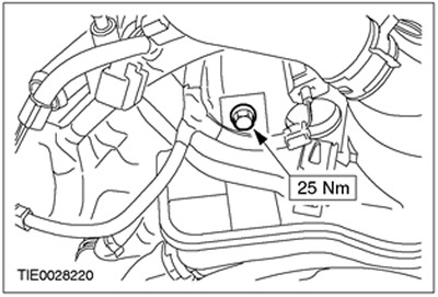
106.
NOTE: Install a new brake booster vacuum pump O-ring.
Install the brake booster vacuum pump.
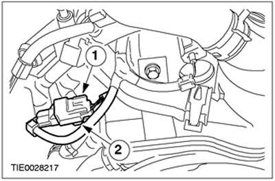
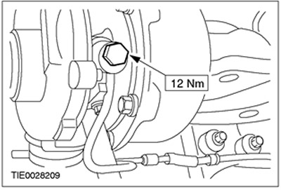
107. Using the special tool, connect the positive crankcase ventilation hose (PCV) to the brake booster vacuum pump.
108. Install the PCV housing.
109. Connect the cylinder head temperature sensor connector (CHT).
- 1.Place the electrical connector.
- 2.Connect the plug connector to the PCV housing.
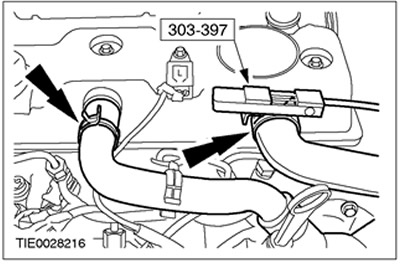
110. Using the special tool, connect the PCV hose to the cylinder head cover.
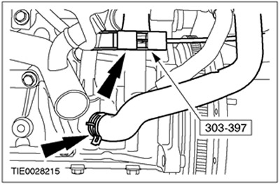
111. Using the special tool, connect the PCV hose to the lower PCV pipeline.
112.
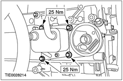
NOTE: Install a new oil cooler gasket.
Install the oil cooler.
113.
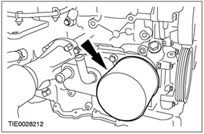
NOTE: Install a new oil filter.
Install the oil filter.
114.
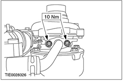
NOTE: Install a new turbocharger oil return pipe O-ring.
Install the turbocharger oil return line.
115.
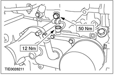
NOTE: Install new turbocharger oil feed line seal washers.
Install the turbocharger oil supply line.
116.
NOTE: Install new turbocharger oil feed line sealing washers.
Connect the oil supply line to the turbocharger.
117. Fill the engine with engine oil.
118. Remove the special tool.
Visitor comments