Special tool
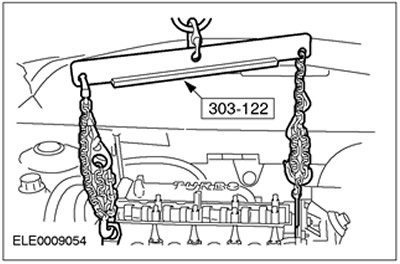
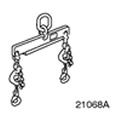 | Engine lift bracket 303-122 (21-068 A) |
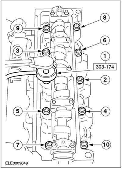
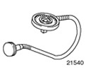 | Protractor for tightening bolts 303-174 (21-540) |
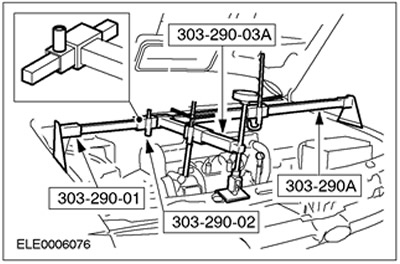
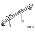 | Engine support yoke 303-290A (21-140A) |
 | Adapter for 303-290A (21-140) 303-290-01 (21-140-01) |
 | Adapter for 303-290A (21-140) 303-290-02 (21-140-02) |
 | Adapter for 303-290A (21-140) 303-290-03A (21-140-03A) |
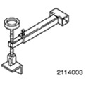
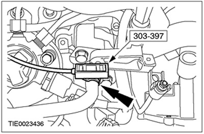
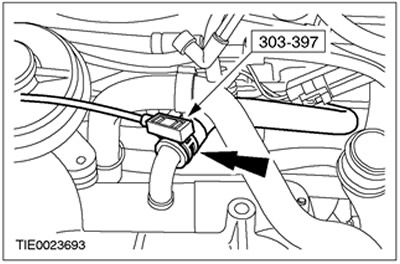
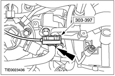
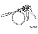 | Clamp remover/installer 303-397 (24-003) |
| Name | Specification |
| Engine oil | WSS-M2C912-A1 |
| Loctite 7070 | |
| Grease ISO 4113 |
Withdrawal
All cars
1.
WARNING: Do not smoke or walk with a lit cigarette or any type of open flame while working on or near fuel related items. In such situations, there are always highly flammable mixtures that can ignite. Failure to follow these instructions may result in injury.
WARNING: Do not make any repairs to the fuel injection system without first reducing the fuel pressure to zero and making sure the fuel temperature is below 30°C. Failure to follow these instructions may result in injury.
WARNING: Do not make any repairs to the fuel injection system while the engine is running. The fuel pressure in the system is approximately 1600 bar. Failure to follow these instructions may result in injury.
CAUTION: Diesel fuel injection equipment is manufactured to very precise tolerances and very close clearances. Therefore, when working with these elements, it is especially important to observe absolute cleanliness. Always insert plugs into any open holes or lines.
CAUTION: Before making any repairs to fuel injection system components, always clean them to prevent foreign material from penetrating into these components.
Using the function «Data logger» («Datalogger») world diagnostic system (WDS), make sure the fuel pressure is reduced to zero and the fuel temperature is below 30°C.
2. Remove the battery and battery tray. Refer to Section 414-01 for more information.
3. Drain the coolant from the cooling system. Refer to Section 303-03 for more information.
4. Remove the timing belt. For more information, refer to the Timing Belt chapter found in this section.
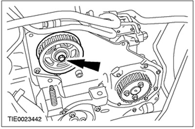
5. Remove the pulley from the camshaft.
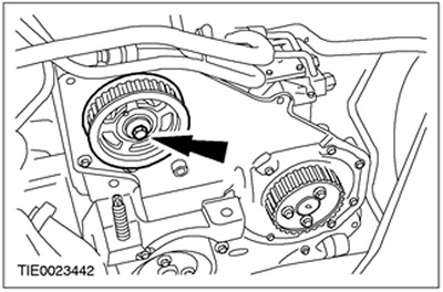
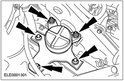
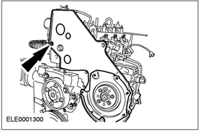
6. Disconnect the rear timing belt cover (for clarity, the engine is shown removed).
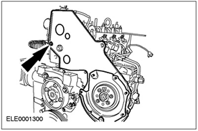
Vehicles manufactured up to 04.2001
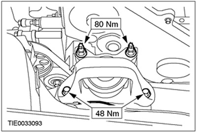
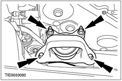
7. Install the front engine mount.
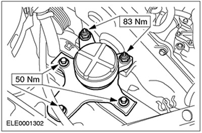
Vehicles manufactured since 04.2001
8. Install the front engine mount.
All cars
9. Remove special tools.
10. Remove the air filter. See Section 303-12 for more information.
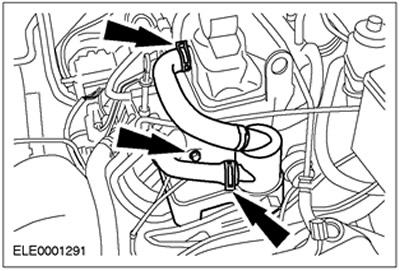
11. Remove the final pipeline of the air filter.
12. Disconnect the vacuum hose from the vacuum diaphragm block of the turbocharger.

13. Disconnect the EGR vacuum hose (EGR) from the EGR valve.
14. Disconnect the EGR vacuum hose.
15. Disconnect the electronic vacuum control valve support bracket from the intake manifold and position it to the side.
16. Remove the oil separator.
17. Establish nuts of covers of bearings of camshafts.
18. Raise and support the vehicle. Refer to Section 100-02 for more information.
19. Disconnect the catalytic converter from the appropriate bracket.
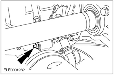
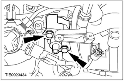
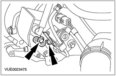
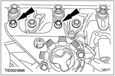
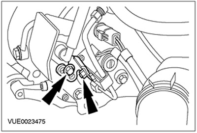
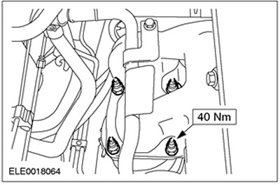
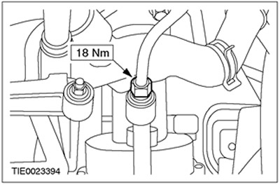
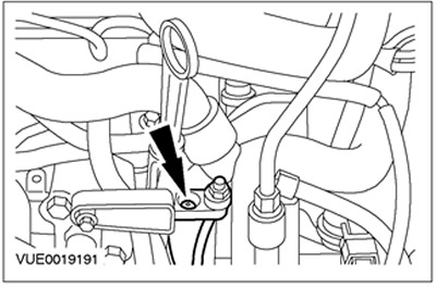
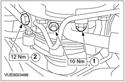
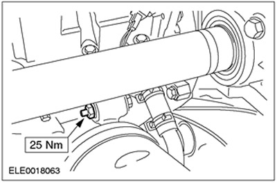
20. Disconnect the supply and return oil lines from the turbocharger.
- 1. Remove the screw securing the oil supply line.
- 2. Turn out bolts of fastening of a returnable oil pipeline.
- Discard gaskets as they are no longer needed.
21. Lower the car.
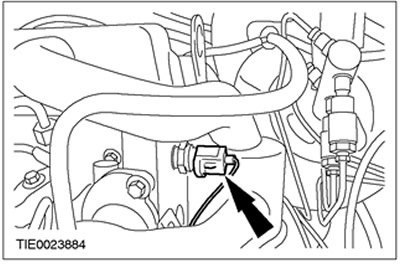
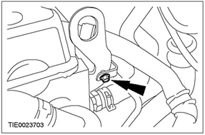
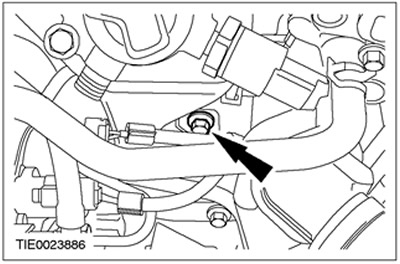
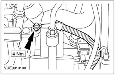
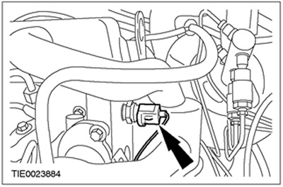
22. Disconnect the plug connector of the oil pressure switch.
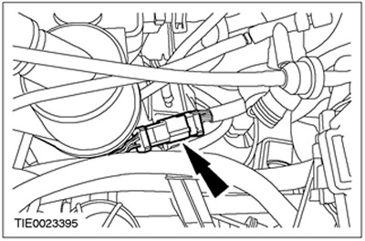
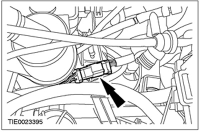
23. Disconnect the plug connector of the engine wiring harness.
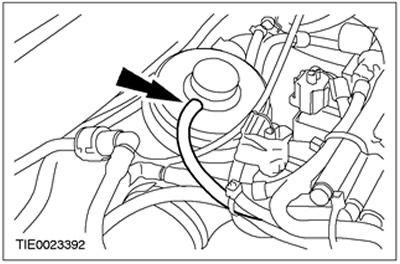
24. Remove the positive crankcase ventilation housing (PCV).
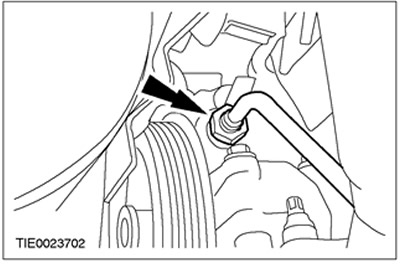
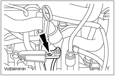
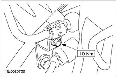
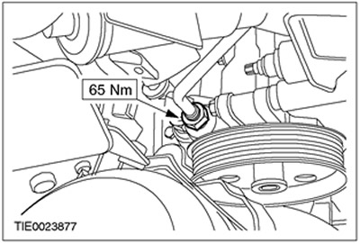
25. Disconnect the high pressure pipe from the power steering pump. Let the liquid drain into a suitable container.
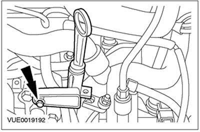
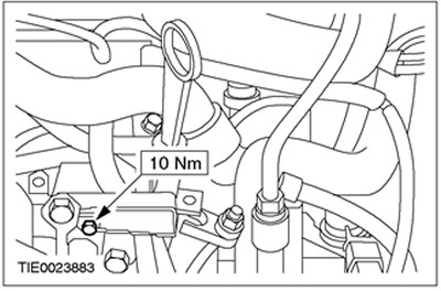
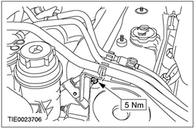
26. Disconnect the power steering high pressure pipe bracket from the timing belt cover stud.
27. Disconnect the power steering high pressure pipe bracket from the lift lug.
28. Disconnect the power steering high pressure line from the bracket and position it aside.
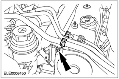
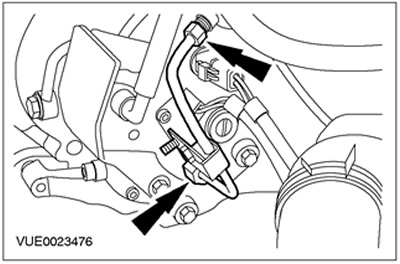
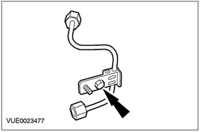
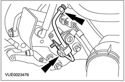
29. Disconnect the glow plug power wire from the glow plug wire terminal block.

30. Disconnect the glow plug wire terminal block.
31. Disconnect the dipstick of the oil level indicator and secure it to the side.
32. Disconnect the vacuum pipeline from the vacuum pump of the vacuum amplifier of brakes.
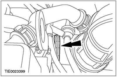
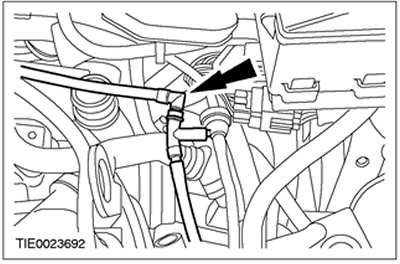
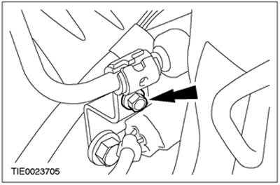
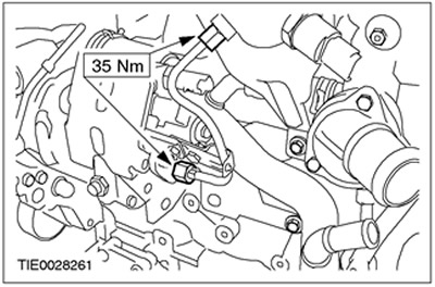
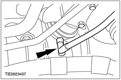
33. Using the special tool, disconnect the upper coolant hose from the thermostat housing.
34. Remove the thermostat housing. Discard the gasket as it is no longer needed.
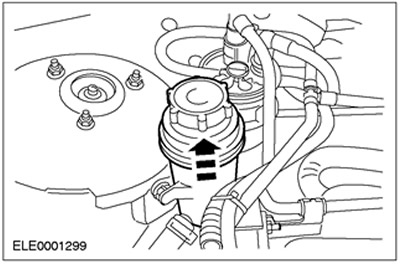
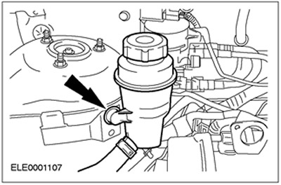
35. Disconnect the power steering fluid reservoir and secure it aside. Let the liquid drain into a suitable container.
36. Disconnect the exhaust manifold from the catalytic converter.

Vehicles with EGR cooler
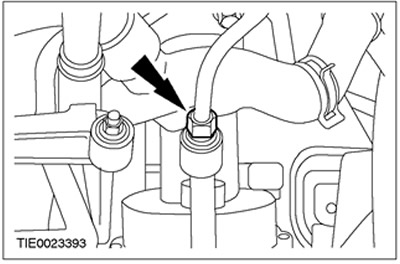
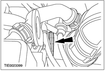
37. Using the special tool, disconnect the upper coolant hose from the EGR cooler.
All cars
38. Clean the area around the fuel manifold, high pressure fuel supply lines and adjacent areas. See Section 303-04A / 303-04B / 303-04C / 303-04D / 303-04E / 303-04F / 303-04G for more information.
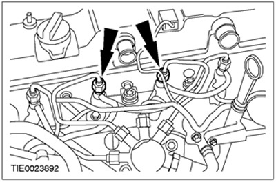
39.
WARNING: To prevent splashing of fuel when disconnecting the fuel return line, cover the fuel injectors with lint-free material. Failure to follow this instruction may result in injury.
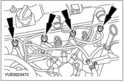
Disconnect the fuel return line from the fuel injectors and install plugs in the return ports of the fuel injectors.

40. Disconnect the fuel injector connectors and cover them with lint-free material to prevent them from being contaminated by the cleaning fluid.

41.
NOTE: Mark the orientation of the clips to ensure they are installed in exactly the same position.
Remove the high pressure fuel line clamp.

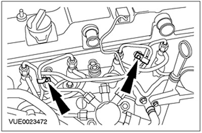
42.
CAUTION: The tool used to release the high pressure fuel supply connections must be installed on top of the connection as there is most of the material. Failure to follow this instruction may result in damage to the pin connection.
NOTE: Apply pressure to the high pressure fuel supply line to keep the nipple in contact with the fuel injector cone when disconnecting the nipple connection.
NOTE: While maintaining pressure on the high pressure fuel supply line, use a vacuum cleaner to remove foreign material from lines and connections.
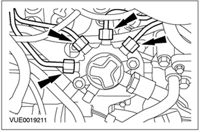
Disconnect the high pressure fuel lines from the fuel injectors.
43. Cover the generator with lint-free material to prevent contamination of the cleaning fluid.
44.
NOTE: Cover the plug connector with a lint-free cloth to prevent cleaning fluid from contaminating it.
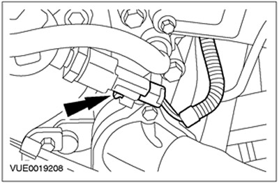
Disconnect the high fuel pressure sensor connector.
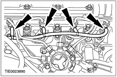
45.
NOTE: Apply pressure to the high pressure fuel supply line to keep the nipple in contact with the fuel manifold cone when disconnecting the nipple connection.
NOTE: While maintaining pressure on the high pressure fuel supply line, use a vacuum cleaner to remove foreign material from lines and connections.
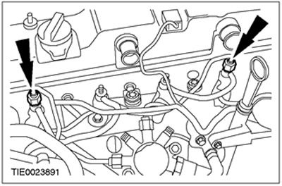
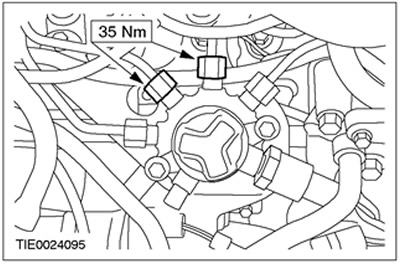
Remove the high pressure fuel lines.
- Install plugs in the open threaded ports of the fuel injectors and fuel manifold.
- Discard the high pressure fuel supply lines as they are no longer needed.
46. Remove the high pressure fuel supply bracket.
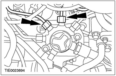
47.
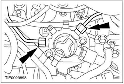
NOTE: Apply pressure to the high pressure fuel supply line to keep the nipples in contact with the high pressure fuel pump and fuel rail cones when disconnecting the nipple connections.
NOTE: While maintaining pressure on the high pressure fuel supply line, use a vacuum cleaner to remove foreign material from lines and connections.
Remove the high pressure fuel supply line. Install plugs in the open threaded ports of the high pressure fuel pump and fuel manifold.
48.
NOTE: Mark the orientation of the clip to ensure it is installed in exactly the same position.
Remove the high pressure fuel line clamp. Discard the high pressure fuel supply line as it is no longer needed.
49. Turn out the bottom bolt of fastening of an arm of a fuel collector.
50. Remove the fuel manifold bracket and fuel manifold.

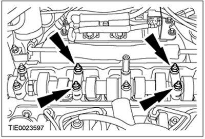
51.
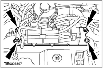
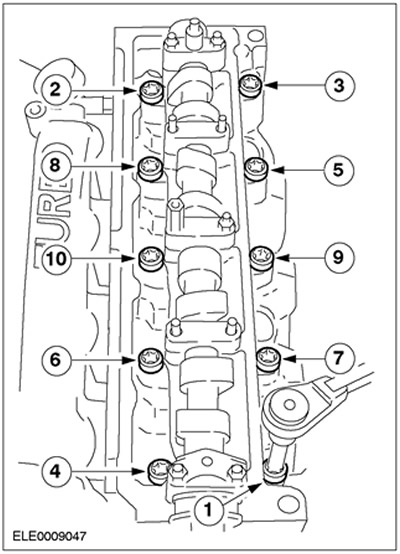
CAUTION: Remove the cylinder head bolts in the sequence shown.
Turn out bolts of a head of cylinders. Discard the bolts as they are no longer needed.
52. Using the special tool, remove the cylinder head. Discard the gasket as it is no longer needed.
Installation
All cars
1.
WARNING: Do not smoke or walk with a lit cigarette or any type of open flame while working on or near fuel related items. In such situations, there are always highly flammable mixtures that can ignite. Failure to follow these instructions may result in injury.
CAUTION: Diesel fuel injection equipment is manufactured to very precise tolerances and very close clearances. Therefore, when working with these elements, it is especially important to observe absolute cleanliness. Always insert plugs into any open holes or lines.
CAUTION: To prevent foreign material from entering fuel system components, always clean before making any repairs to such components.
Clean the mating surfaces of the cylinder head and cylinder block using Loctite 7070.
2. Check the cylinder head for deformation of the mating surface. Refer to Section 303-00 for more information.
3.
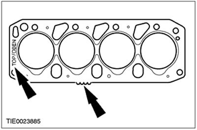
CAUTION: The thickness of the new cylinder head gasket must match the thickness of the «old» (hole/prong markings).
NOTE: Marking «TOP/OBEN» («Up»).
Install a new cylinder head gasket.
4.
NOTE: Pistons must not be at top dead center. Make sure that the special tool fits into the grooves on the ends of the camshafts.
Install the cylinder head to the cylinder block using the special tool when installing. Remove the special tool.

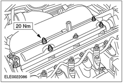
5.
CAUTION: Use new, unlubricated cylinder head bolts.
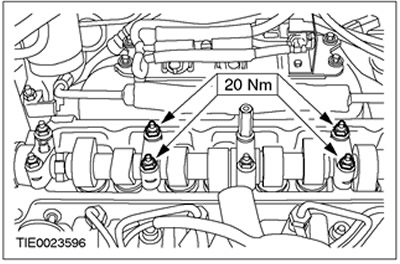
Tighten the cylinder head bolts in four stages.
- Using the special tool, tighten the bolts in the sequence shown
- Stage 1: 20 Nm
- Stage 2: 54 Nm
- Stage 3: 90 degrees
- Stage 4: short bolts: 70 degrees, long bolts: 90 degrees
6.
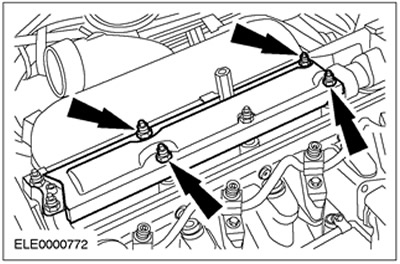
NOTE: Do not tighten the fuel rail bracket mounting bolts at this stage.
Install the fuel manifold bracket and fuel manifold.
7.
NOTE: Do not tighten the fuel rail bracket bolt at this stage.
Install the lower fuel rail bracket bolt.

8.
NOTE: Use new high pressure fuel feed nipple connections.
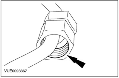
Lubricate the threads of the high pressure fuel supply line connections with clean ISO 4113 grease supplied in the high pressure fuel supply line spare parts kit.

9.
CAUTION: Do not allow the mating ends of the high-pressure fuel supply line pin to strike, as this may damage the fuel line and allow foreign material to enter the fuel injection system.
NOTE: Do not tighten the high pressure fuel feed nipple connections at this stage.
NOTE: Apply pressure to the high pressure fuel supply line to keep the nipple in contact with the fuel injector cone when hand-tightening the nipple connection.
NOTE: The yellow bead on the high pressure fuel supply line is on the injector side and the blue bead on the fuel manifold side.
Connect the No. 1 and No. 4 high pressure fuel feed lines to the fuel injectors.
10.
CAUTION: Do not allow the mating ends of the high pressure fuel supply line pin to strike as this may damage the fuel line and allow foreign material to enter the fuel injection system.
NOTE: Do not tighten the high pressure fuel feed nipple connections at this stage.
NOTE: Apply pressure to the high pressure fuel supply line to keep the nipple in contact with the fuel injector cone when hand-tightening the nipple connection.
Connect the No. 1 and No. 4 high pressure fuel feed lines to the fuel rail.
11.
NOTE: Be sure to install the clip in the same position it was in before removal.
Install the clamp on the high pressure fuel supply line.

12.
NOTE: Use a new high pressure fuel supply line connection.
Lubricate the threads of the high pressure fuel supply line connections with clean ISO 4113 grease supplied in the high pressure fuel supply line spare parts kit.
13.
CAUTION: Do not allow the mating ends of the high-pressure fuel supply line pin to strike, as this may damage the fuel line and allow foreign material to enter the fuel injection system.
NOTE: Do not tighten the high pressure fuel supply pipe nipple at this stage.
NOTE: Apply pressure to the high pressure fuel supply line to keep the nipple in contact with the fuel injector cone when hand-tightening the nipple connection.
NOTE: The yellow bead on the high pressure fuel supply line is on the injector side and the blue bead on the fuel manifold side.
Install the high pressure fuel supply line.
14.
CAUTION: Do not allow the mating ends of the high pressure fuel supply line pin to strike as this may damage the fuel line and allow foreign material to enter the fuel injection system.
NOTE: Do not tighten the high pressure fuel feed nipple connections at this stage.
NOTE: Apply pressure to the high pressure fuel supply line to keep the nipple in contact with the fuel injector cone when hand-tightening the nipple connection.
NOTE: The yellow bead on the high pressure fuel supply line is on the injector side and the blue bead on the fuel manifold side.
Connect the high pressure fuel supply lines of cylinders 2 and 3 to the fuel injectors.
15.
CAUTION: Do not allow the mating ends of the high-pressure fuel supply line pin to strike, as this may damage the fuel line and allow foreign material to enter the fuel injection system.
NOTE: Do not tighten the high pressure fuel feed nipple connections at this stage.
NOTE: Apply pressure to the high pressure fuel supply line to keep the nipple in contact with the fuel injector cone when hand-tightening the nipple connection.
Connect the high pressure fuel supply lines of cylinders 2 and 3 to the fuel manifold.
16. Connect the fuel return line to the fuel injectors.
17.
NOTE: Be sure to install the clips in the same position from which they were removed.
Install the high pressure fuel supply line clamps.
18. Install the high pressure fuel line bracket.
19. Install the fuel manifold bracket and fuel manifold.
20. Install the lower fuel manifold bracket bolt.
21. Tighten cylinders 1 and 4 high pressure fuel feed lines to fuel injectors.
22. Tighten cylinders 1 and 4 high pressure fuel feed lines to fuel manifold.

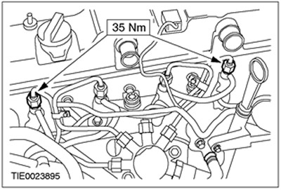
23. Install the high pressure fuel supply line.
24. Tighten cylinders 2 and 3 high pressure fuel feed lines to fuel injectors.
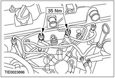
25. Tighten cylinders 2 and 3 high pressure fuel feed lines to fuel manifold.
Vehicles with EGR cooler
26. Using the special tool, connect the upper coolant hose to the EGR cooler.

All cars
27. Connect the exhaust manifold to the catalytic converter.
28. Fix a tank of a working liquid of the amplifier of a steering.
29. Connect the high fuel pressure sensor connector.

30.
NOTE: Use a new gasket.
Install the thermostat housing.

31. Using the special tool, connect the upper coolant hose to the thermostat housing.
32. Connect the vacuum pipeline to the vacuum pump of the vacuum amplifier of brakes.
33. Connect the dipstick of the oil level indicator.
34. Connect the glow plug wire terminal block.
35. Connect the glow plug power wire to the glow plug wire terminal block.
36. Connect the power steering high pressure line to the bracket.
37. Connect the power steering high pressure pipe bracket to the lift lug.

38. Connect the power steering high pressure pipe bracket to the timing belt cover stud.
39. Connect the high pressure pipe to the power steering pump.
40. Connect the plug connector of the engine wiring harness.
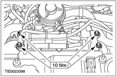
41.
NOTE: Install the clamp at a 45 degree angle to the horizontal.
Install the PCV housing.

42. Connect the plug connector of the oil pressure switch.
43. Raise and support the vehicle. Refer to Section 100-02 for more information.
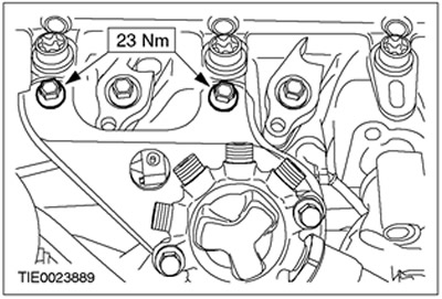
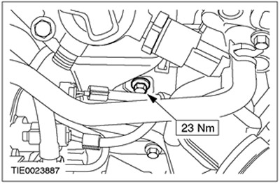
44.
NOTE: Use new gaskets.
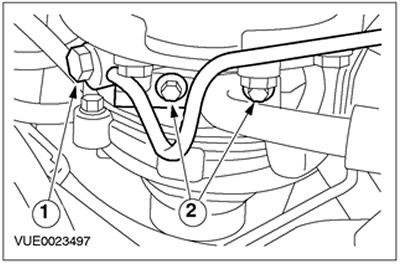
Connect the oil supply and return lines to the turbocharger.
- 1.Install the oil return pipe mounting bolt.
- 2.Install the oil supply line mounting bolts.
45. Connect the catalytic converter to the appropriate bracket.
46. Lower the car.
47. Remove the bearing cap nuts.
48. Install the oil separator.
49. Connect the EVA support bracket to the intake manifold and position it aside.
50. Connect the EGR vacuum hose.

51. Connect the EGR vacuum hose to the EGR valve.

52. Connect the vacuum hose to the vacuum diaphragm block of the turbocharger.
53. Install the air filter outlet pipe.
54. Install the air filter. See Section 303-12 for more information.
55. Install special tools.

Vehicles manufactured up to 04.2001
56. Remove the front engine mount.
Vehicles manufactured since 04.2001
57. Remove the front engine mount.
All cars
58. Install the rear timing belt cover (for clarity, the engine is shown removed).
59.
NOTE: Do not tighten the camshaft pulley bolt at this stage.
Install the camshaft pulley.
60. Put on the timing belt. For more information, refer to the Timing Belt chapter found in this section.
61. Fill the cooling system with coolant and bleed the air from the system. Refer to Section 303-03 for more information.
62. Top up power steering system fluid and bleed air from system. Refer to Section 211-00 for more information.
63. Install the battery shelf and connect the battery. Refer to Section 414-01 for more information.
64. Change engine oil and oil filter.
Visitor comments