Special tool
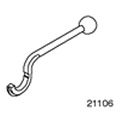 | Valve Adjustment Compression Tool 303-195 (21-106) |
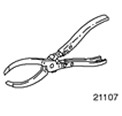 | Pliers for valve shims 303-196 (21-107) |
General equipment: Set of probes.
| Name | Specification |
| Shims |
1. Remove the cylinder head cover. For more information, refer to the Cylinder Head Cover chapter available in this section.
2. Remove the oil separator.
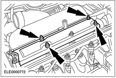
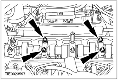
3. Reinstall bearing cap nuts.
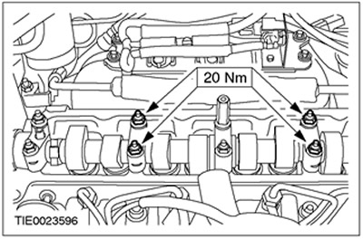
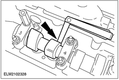
4. Measure the valve clearance.
- Turn the crankshaft so that the pair of cams of the adjustable cylinder is facing up.
- Check valve clearance and record results.
- If the clearance at the installation location of any of the shims is out of range, replace that shim as described in the next paragraph.
5.
NOTE: Rotate the crankshaft another 90 degrees.
NOTE: Adjustable cylinder piston must not be at top dead center.
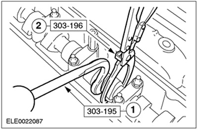
Replace shim.
- 1.Using the special tool, simultaneously push down the tappets of the two valves.
- 2. Using the special tool, remove the shim.
- Pay attention to the thickness of the shim marked on the back of the shim.
- Install a new shim to get the correct valve clearance.
6. Remove the bearing cap nuts.
7. Install the oil separator.
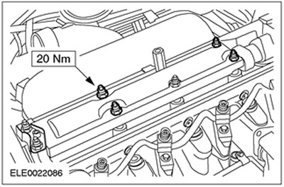
8. Install the cylinder head cover. For more information, refer to the Cylinder Head Cover chapter available in this section.
Visitor comments