This diesel engine, which is offered in 55 kW (75 HP) and 66 kW (90 HP), based on the famous swirl chamber diesel engine, but enhanced with the latest developments, including charge air cooling and direct fuel injection.
Therefore, this engine meets the EEC D3 emission standard and all other requirements for the latest generation of engines in terms of fuel consumption, smooth operation, versatility, dynamics and power output.
Engine codes
Codes for Endura-DI engines:
- 55 kW / 75 hp - BHDA
- 66 kW (90 HP) - C9DB
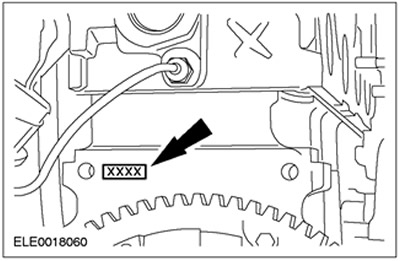
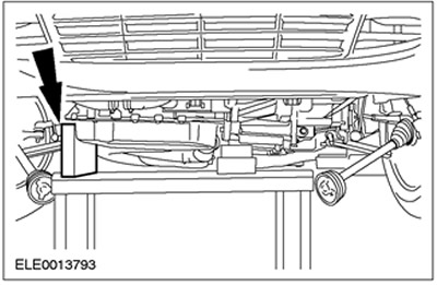
Engine code location on Endura-DI engine block:
Crankshaft
The crankshaft, supported by five main bearings, has thrust half rings on the third main bearing, which determine the axial clearance of the crankshaft.
Timing sprocket located on the crankshaft
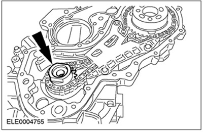
An asterisk located on the crankshaft drives the high pressure fuel pump sprocket through a chain drive (injection pump). The sprocket is fixed on the crankshaft with a central bolt that creates a clamping force.
Belt drive of the gas distribution mechanism
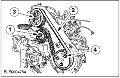
| Pos. | Spare Part No | Name |
| 1 | - | Timing belt tensioner |
| 2 | - | timing belt |
| 3 | - | Camshaft Pulley |
| 4 | - | High pressure fuel pump pulley |
The timing belt is driven by the high pressure fuel pump pulley and transmits valve timing information to the top camshaft.
CAUTION: Because A new timing belt will stretch considerably when first installed, the adjustment instructions must be followed exactly.
Belt tension is provided by an automatic tensioner. The initial tension setting is carried out using the adjusting cam.
The pulley is fixed on the tapered shank of the camshaft. The required force to fix the pulley on the camshaft is provided by a central bolt.
Valve lifter, shims (shims)
"Team" about the valve timing is transmitted to the valve springs by means of eight pushers.
CAUTION: When installing shims, the labels on the shims must face the tappets.
Shims are used to adjust valve clearances. The thickness of each gasket is indicated on its reverse side.
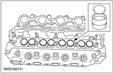
Cylinder head
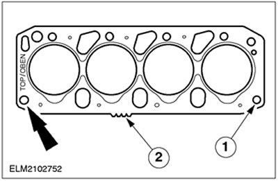
| Pos. | Spare Part No | Name |
| 1 | - | Hole for guide sleeve |
| 2 | - | Gasket Thickness Identification |
Cylinder head gaskets are available in various thicknesses. Depending on the protrusion of the pistons on the engine, a gasket of a certain thickness must be used. The thickness can be determined by the teeth on the edge of the gasket.
CAUTION: Completely clean the gasket and mating surfaces. Do not use sharp objects for cleaning.
Cylinder head gasket - type MLS gasket (laminated steel). The gasket consists of three steel layers. The steel layers have an outer rubber coating. Due to its design, the durability of the gasket is increased, and as a result of the fact that the gasket does not break in during installation, the cylinder head bolts can be inserted with a lower clamping force. However, due to the rubber surface, the gasket is also more susceptible to grooves and therefore the surface should be pre-cleaned without the use of sharp objects.
Crankshaft oil seals
NOTE: The crankshaft rear oil seal comes with a locating sleeve. It exposes the oil seal against the rear flange of the crankshaft.
NOTE: The position of the crankshaft rear oil seal holder must be aligned using a special tool.
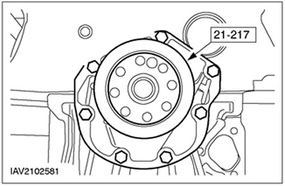
CAUTION: If the mounting sleeve is removed too soon, the oil seal will shrink and become unusable.
Front and rear oil seals are made of PTFE. They must be clean when installed (unoiled).
Both oil seals are supplied with a locating sleeve. The bushing should not be removed until the assembly procedure is complete.
Crankcase ventilation
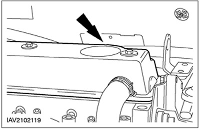
The crankcase ventilation valve is located on the top surface of the cylinder head cover. For optimum engine performance, this valve and all PCV hoses must always be clean and free of any dirt inside.
Oil sump
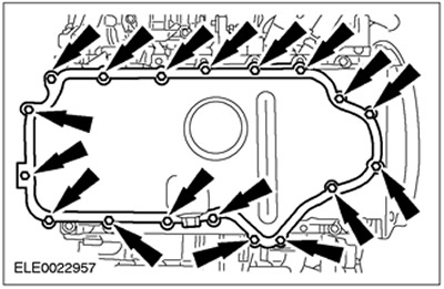
The oil sump is made of steel. It is sealed with silicone based sealant (WSE-M4G-323-A6).
CAUTION: When removing the front engine mount, do not place a jack to support the engine under the oil sump.
CAUTION: Mount the engine/gearbox assembly with the oil pan flange on wooden blocks so as not to stress the oil pan.
Visitor comments